
In the realm of precision gear manufacturing, gear honing stands out as a vital finishing process that significantly enhances the surface quality, accuracy, and performance of hardened gears. Traditional gear honing methods, particularly worm-type honing, have been widely adopted due to their efficiency and cost-effectiveness. However, these methods often produce parallel grooves on the tooth flank, which can adversely affect motion accuracy, contact precision, and lubricant retention in gear systems. To address these limitations, I have explored an advanced variant known as oscillating worm gear honing, which incorporates a harmonic vibration along the gear’s tooth direction. This article presents a comprehensive analysis of the meshing patterns generated during this innovative gear honing process, focusing on the trajectory and纹路 forms under various honing parameters. By delving into the mathematical models and parametric influences, I aim to provide a theoretical foundation for optimizing gear honing operations, ultimately leading to improved gear performance and longevity.
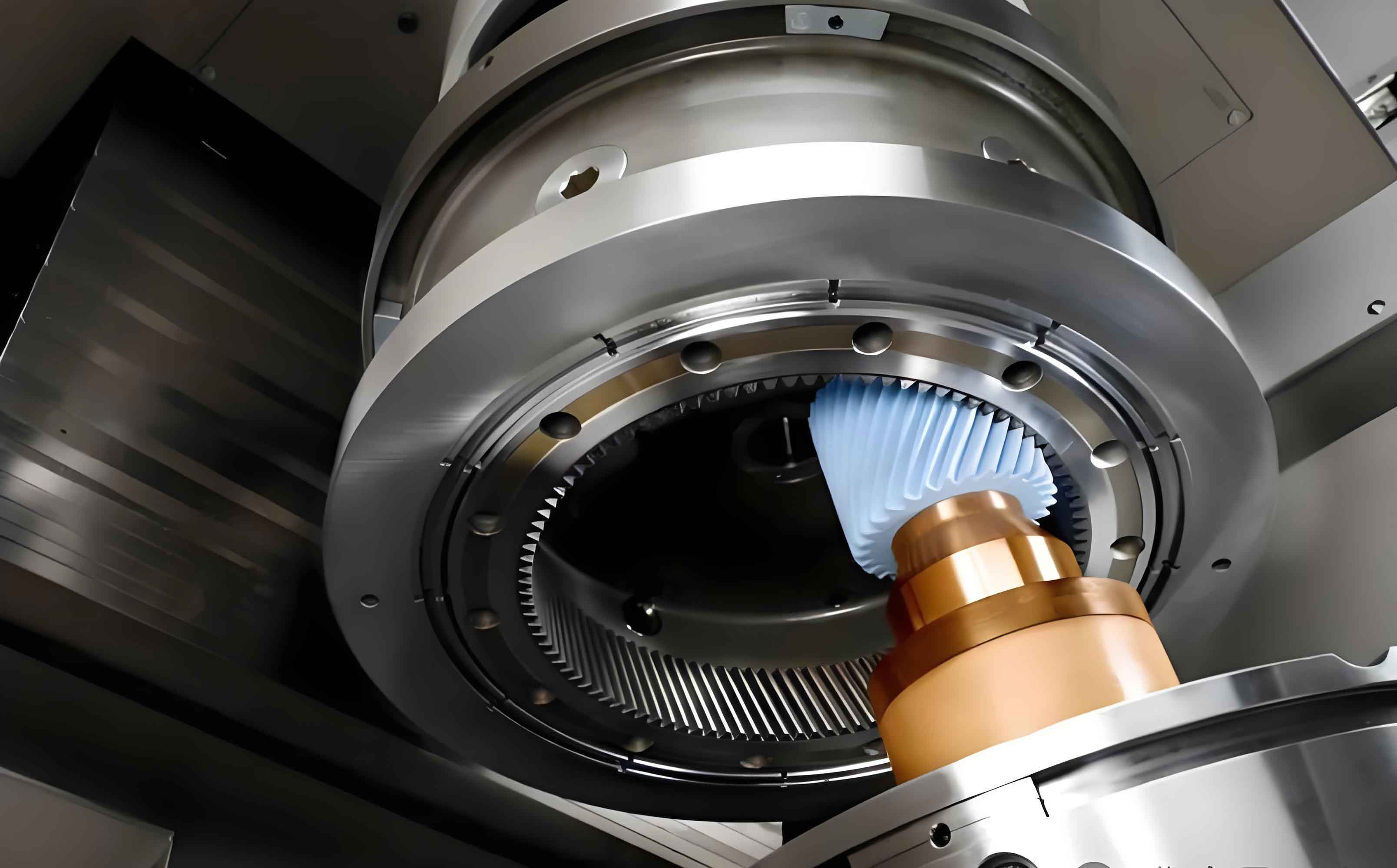
The oscillating worm gear honing process builds upon conventional worm honing by superimposing a sinusoidal oscillation onto the worm tool’s motion. As illustrated in the figure, the setup involves a worm honing tool, typically with a single start (z₁ = 1) and module m, engaging with a gear of tooth number z₂. The key motion parameters governing this gear honing process include: the rotational speed of the worm honing tool n₁ (in rpm), the oscillation frequency f (in Hz), the oscillation amplitude a (in mm), and the axial feed per revolution s (in mm/r). These parameters collectively dictate the meshing patterns on the gear tooth surface, which are critical for determining the effectiveness of the gear honing operation. In this analysis, I will derive the meshing trajectory equations, examine the resulting patterns, and discuss how parameter selection influences outcomes in gear honing applications.
To understand the meshing trajectory in oscillating worm gear honing, I first consider the kinematic engagement between the worm tool and the gear. The worm tool is essentially an Archimedes worm, which, during gear honing, simulates a rack-and-gear meshing scenario. In a coordinate system attached to the gear, the involute equation of the gear tooth profile is expressed as:
$$ \mathbf{r} = R_b \left[ (\cos \theta + \theta \sin \theta) \mathbf{i} + (\sin \theta – \theta \cos \theta) \mathbf{j} \right] $$
where \( R_b \) is the base circle radius of the gear, and \( \theta \) is the involute angle. The tangential vector along the tooth profile is given by:
$$ \mathbf{r}’ = \frac{d\mathbf{r}}{d\theta} = R_b \omega_2 (\cos \theta \mathbf{i} + \sin \theta \mathbf{j}) $$
Here, \( \omega_2 \) represents the angular velocity of the gear. Assuming meshing initiates at the tooth tip, the arc displacement \( s \) along the tooth height direction from tip to root can be derived by integrating the tangential motion. Given the uniform rotation of the gear, where \( \theta = \omega_2 (t_0 – t) \) with \( t_0 \) as a time constant and \( t \) as time, the displacement equation becomes:
$$ s = \frac{R_b}{2} \omega_2 (2t_0 – t)t $$
The tangential velocity \( v_t \) of the meshing point along the tooth height is obtained by differentiating \( s \) with respect to time:
$$ v_t = \frac{ds}{dt} = R_b \omega_2^2 (t_0 – t) $$
This velocity is maximum at the tooth tip and diminishes toward the root, approaching zero near the base circle. Concurrently, the oscillation of the worm tool is described by a simple harmonic motion:
$$ y = a \sin(2\pi f t) $$
where \( y \) denotes the displacement along the tooth width direction. Combining these equations, the meshing trajectory on the gear tooth surface can be parameterized. When the tooth surface is developed into a plane, the trajectory manifests as a cosine wave with variable pitch, transitioning from a maximum at the tip to a minimum at the root. To characterize this trajectory, I define the nominal mesh half-angle \( \eta \) at the midpoint of the amplitude on the pitch circle:
$$ \eta = \arctan\left( \frac{v_{tR}}{v_{omax}} \right) $$
Here, \( v_{tR} \) is the tangential velocity at the pitch circle, and \( v_{omax} = 2\pi f a \) is the maximum oscillation velocity. From the above relations, \( \eta \) can be expressed in terms of the gear honing parameters as:
$$ \eta = \arctan\left( \frac{n_1 m z_2 \sin 2\alpha}{60 a f} \right) $$
where \( \alpha \) is the pressure angle. The angle \( \eta \) reflects the steepness of the trajectory curve; a smaller \( \eta \) indicates a steeper, more densely packed wave, while a larger \( \eta \) corresponds to a flatter curve. This parameter is crucial in gear honing as it influences the honing intensity and surface finish quality.
During the gear honing process, as the worm tool feeds axially with feed rate \( s \), multiple meshing trajectories accumulate to form a pattern on the tooth surface. The meshing pattern depends not only on the shape of individual trajectories but also on the ratio \( a/s \) and the phase difference \( \phi \) between adjacent trajectories. To analyze this, I introduce parameters \( K \), \( K_1 \), and \( K_2 \):
$$ K = \frac{60 f z_2}{n_1} = K_1 + K_2 $$
where \( K \) represents the number of oscillations per revolution of the gear, \( K_1 \) is the integer part, and \( K_2 \) is the fractional part. The phase lag \( \phi \) between consecutive honing strokes is then:
$$ \phi = 2\pi (1 – K_2) $$
Based on different combinations of parameters, various meshing patterns emerge in gear honing. I summarize these patterns and their characteristics in the following table, which serves as a guide for selecting optimal parameters in gear honing applications.
| Pattern Type | Description | Typical Parameter Conditions | Impact on Gear Honing Quality |
|---|---|---|---|
| Uniform Ripple Pattern | Regular, evenly spaced wave-like lines | \( \phi = 0 \) or \( 2\pi \), moderate \( \eta \) (e.g., 15°–30°), \( a/s \approx 1-2 \) | Ideal for error correction and uniform material removal; enhances lubricant retention. |
| Diamond Pattern | Crisscrossing lines forming diamond-shaped网格 | \( \phi = \pi \), small \( s \), \( a/s > 1 \), moderate \( \eta \) | Provides good surface finishing and contact area distribution; suitable for precision gear honing. |
| Overlapping Wave Pattern | Uneven overlaps creating dense and sparse regions | \( \phi = \pi/2 \) or \( 3\pi/2 \), \( a/s > 1 \), small \( \eta \) | Poor; leads to inconsistent honing and potential surface defects; should be avoided in gear honing. |
The factors influencing meshing patterns in gear honing are primarily the nominal mesh half-angle \( \eta \), the amplitude-to-feed ratio \( a/s \), and the phase difference \( \phi \). Let me examine each factor in detail, emphasizing their interplay in the context of gear honing.
Nominal Mesh Half-Angle \( \eta \): This angle determines the density and steepness of the trajectory waves along the tooth height. In gear honing, a smaller \( \eta \) results from higher oscillation frequencies or amplitudes, leading to denser waves that can enhance the honing action by covering more surface area. However, excessively small \( \eta \) values may cause rapid fluctuations in cutting speed, potentially inducing vibrations and reducing honing accuracy. Conversely, a larger \( \eta \), often associated with lower frequencies or amplitudes, produces flatter waves that might not fully exploit the benefits of vibration in gear honing. Experimental studies suggest an optimal range for \( \eta \) between 10° and 25° for effective gear honing, balancing pattern density and process stability.
Amplitude-to-Feed Ratio \( a/s \): This ratio directly affects the overlap and density of the meshing pattern. A higher \( a/s \) increases pattern density without sacrificing productivity, as the feed rate \( s \) can be maintained. For instance, in gear honing, if \( a/s > 1 \), the oscillation covers multiple feed increments, creating interlaced patterns. However, if \( a/s \) is too high (e.g., >3), it may lead to excessive overlap and uneven material removal. A practical recommendation for gear honing is to set \( a/s \) between 1 and 2.5, ensuring sufficient pattern complexity while maintaining control over the honing process.
Phase Difference \( \phi \): The phase difference governs the uniformity of the meshing pattern. When \( \phi = 0 \) (or \( 2\pi \)), the pattern is perfectly periodic, resulting in uniform ripples—this is highly desirable in gear honing for consistent surface treatment. When \( \phi = \pi \), a diamond pattern forms, which also offers benefits in distributing honing marks. However, when \( \phi = \pi/2 \) or \( 3\pi/2 \), especially with \( a/s > 1 \), the pattern becomes irregular with overlaps, which can compromise gear honing quality by creating stress concentrations. Thus, in gear honing parameter selection, aiming for \( \phi \) near 0 or \( \pi \) is advisable.
To further elucidate the parametric influences, I present a detailed analysis using numerical simulations. Consider a standard gear with module \( m = 5 \) mm, tooth number \( z_2 = 40 \), and honing parameters: \( n_1 = 160 \) rpm, \( s = 1.16 \) mm/r. By varying \( f \) and \( a \), different meshing patterns emerge. The table below summarizes the effects of parameter variations on \( \eta \) and pattern type, providing insights for optimizing gear honing processes.
| Parameter Change | Effect on \( \eta \) | Effect on Meshing Pattern | Practical Implication for Gear Honing |
|---|---|---|---|
| Increase oscillation frequency \( f \) | Decreases \( \eta \) | Makes pattern denser and steeper; may shift \( \phi \) | Use moderate \( f \) (e.g., 5–15 Hz) to balance pattern density and tool life. |
| Increase oscillation amplitude \( a \) | Decreases \( \eta \) | Increases pattern amplitude; enhances overlap at high \( a/s \) | Select \( a \) based on tooth width; typical \( a \) ranges from 0.5 to 3 mm in gear honing. |
| Increase axial feed \( s \) | No direct effect on \( \eta \) | Reduces pattern density; increases productivity | Adjust \( s \) to achieve desired cycle time, but ensure \( a/s \) remains optimal. |
| Increase worm speed \( n_1 \) | Increases \( \eta \) | Flattens pattern; reduces honing intensity | Set \( n_1 \) based on material and tool specifications; often 100–300 rpm for gear honing. |
The relationship between parameters can be leveraged to achieve specific patterns in gear honing. For example, to obtain a uniform ripple pattern with \( \phi = 0 \), one can set \( K \) as an integer, leading to:
$$ f = \frac{n_1 K}{60 z_2} $$
where \( K \) is an integer. Similarly, for a diamond pattern with \( \phi = \pi \), \( K \) should be a half-integer. These formulas enable precise control over meshing patterns in gear honing, facilitating tailored solutions for different gear types.
Beyond pattern analysis, the oscillating worm gear honing process offers substantial benefits. The multi-directional honing action helps mitigate periodic errors from prior machining steps, such as grinding or hobbing, thereby improving gear accuracy. Additionally, the net-like patterns enhance oil retention on tooth flanks, which is critical for lubricated gear operations, reducing friction, wear, and noise. In high-demand applications like automotive transmissions or industrial gearboxes, these advantages translate to extended service life and enhanced reliability. However, implementing this gear honing technique requires careful attention to tool design and process control. The oscillation mechanism must maintain consistent amplitude and frequency, and tool wear should be monitored to prevent pattern degradation over time. Future research in gear honing could explore adaptive control systems that dynamically adjust parameters based on real-time sensor feedback, ensuring consistent quality throughout production runs.
In conclusion, the analysis of meshing patterns in oscillating worm gear honing reveals a complex interplay between motion parameters and surface outcomes. Through mathematical modeling and parametric studies, I have demonstrated how vibration can be harnessed to create beneficial纹路 that elevate gear performance. The key parameters—\( \eta \), \( a/s \), and \( \phi \)—serve as critical levers for optimizing the gear honing process. By selecting parameters that yield uniform or diamond patterns, manufacturers can achieve superior surface integrity, accuracy, and durability in gears. As the gear industry continues to evolve, further investigation into advanced gear honing techniques, including real-time monitoring and AI-driven optimization, will unlock new potentials for precision manufacturing. This exploration underscores the importance of gear honing as a transformative process in modern engineering, paving the way for more efficient and reliable gear systems worldwide.