
In this study, I present a comprehensive investigation into the meshing performance of a novel transmission system: the tapered roller enveloping end-face meshing worm gear drive. This transmission system offers distinct advantages, such as a high number of simultaneously meshing tooth pairs and the capability to eliminate clearance, which are critical for precision and high-load applications. To explore these benefits, I established a mathematical model of the meshing process based on the principles of differential geometry and the theory of gearing. This model allowed me to derive the meshing function, the worm gear tooth surface equation, and the primary formulas for evaluating meshing performance. Using MATLAB, I systematically analyzed the effects of three key geometric parameters—the small-end radius of the tapered roller, the throat diameter coefficient, and the half-cone angle of the roller—on four critical performance indicators: induced normal curvature, lubrication angle, relative entrainment velocity, and self-rotation angle. My analysis confirms that this worm gear drive exhibits superior meshing characteristics, including excellent load capacity and robust lubrication conditions, making it a promising candidate for advanced mechanical systems.
The worm gear is a fundamental component for transmitting motion and power between non-intersecting shafts, often relying on the friction between conjugate tooth surfaces. This transmission method is widely used in aerospace, medical devices, construction, marine equipment, and robotics due to its smooth operation, high transmission ratio, compact structure, and resistance to impact loads. However, compared to other gear drives, worm gear systems frequently suffer from lower efficiency and reduced load capacity. The primary cause of these drawbacks is the inevitable relative sliding between the meshing tooth surfaces. Under poor working conditions with high relative sliding velocities, this friction leads to severe wear and heat generation, which can deteriorate the lubrication state of the worm gear system.
While improvements in lubrication have enhanced the efficiency of many worm gear drives under certain conditions, statistics indicate that most worm gear drives in practical industrial applications operate under partial elastohydrodynamic lubrication. This means that direct contact between asperities on the two meshing tooth surfaces is common. As long as such metallic contact exists, relative sliding remains a persistent issue. To address this challenge, researchers have proposed various solutions and novel worm gear configurations. My work focuses on one such innovation: the tapered roller enveloping end-face meshing worm gear drive.
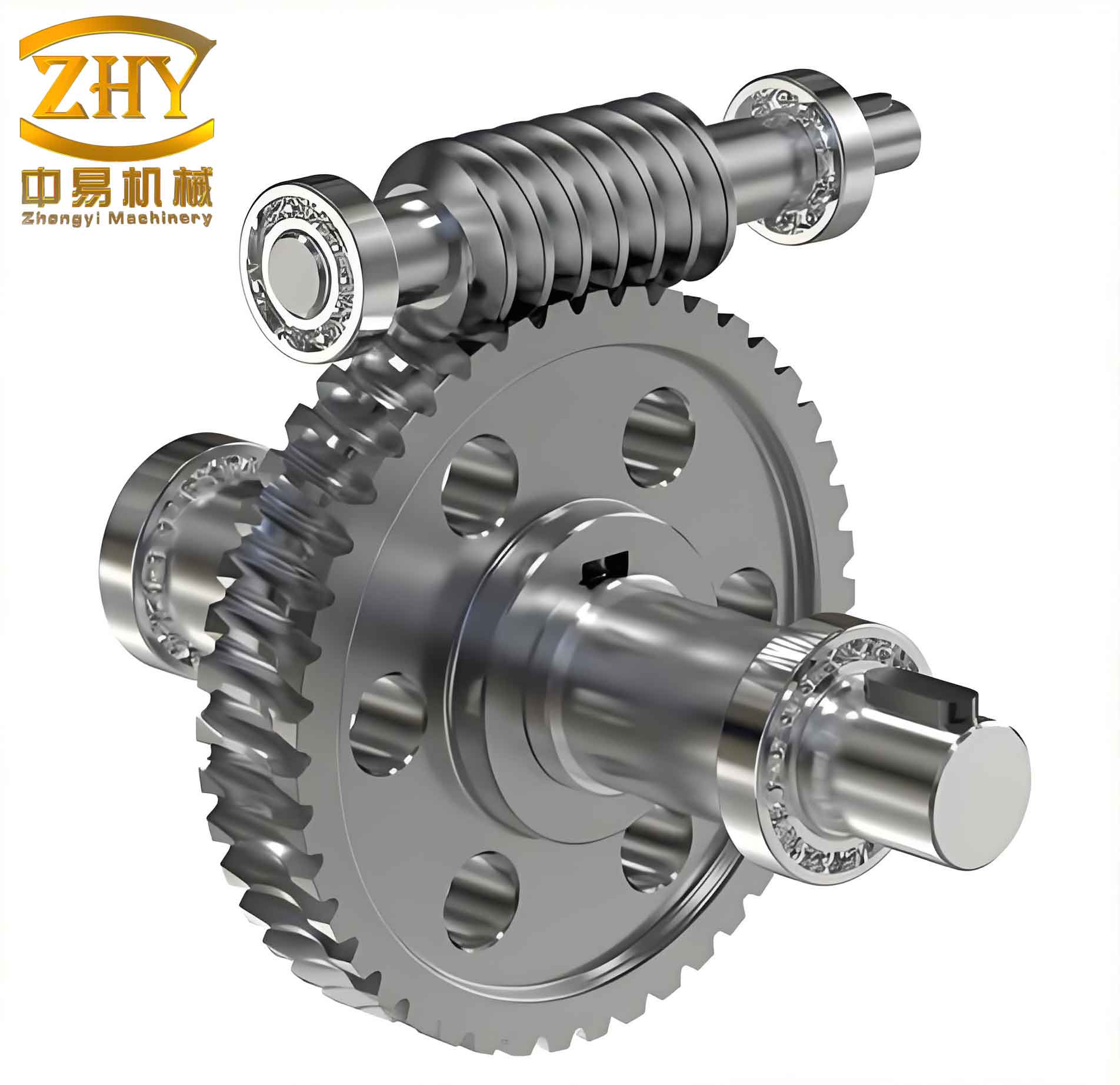
In this design, the worm wheel teeth are conical rollers (tapered rollers) that can rotate around their own axes. The worm is a toroidal (hourglass-shaped) surface generated by enveloping the conical surfaces of these rotating rollers. To minimize relative sliding, needle bearings are installed between the roller and its shaft, and axial rolling bearings are placed at the large end of the roller. This effectively converts much of the sliding motion into rolling motion. This concept builds upon previous work on tapered roller enveloping toroidal worm drives and introduces the end-face engagement principle. The worm gear is characterized by being divided into two segments and engaging on the end face. The worm wheel teeth are active moving teeth connected to the wheel body via rolling bearings.
I structured this study to first establish the mathematical model of the worm gear transmission, including the coordinate systems and transformation matrices. Next, I derived the governing equations for velocity, meshing, and tooth surface generation. Finally, I developed formulas for performance evaluation and conducted a parametric analysis.
Mathematical Model of the Worm Gear Transmission
Establishment of Coordinate Systems
Based on differential geometry and gearing theory, I established several coordinate systems for the tapered roller enveloping end-face meshing worm gear drive. The static coordinate systems are σ₁(i₁, j₁, k₁) for the worm and σ₂(i₂, j₂, k₂) for the worm wheel. The moving coordinate systems are σ₁′(i₁′, j₁′, k₁′) for the worm and σ₂′(i₂′, j₂′, k₂′) for the worm wheel. In these systems, k₁ = k₁′ is the rotation axis of the worm, and k₂ = k₂′ is the rotation axis of the worm wheel. The angular velocity vectors are ω₁ for the worm and ω₂ for the worm wheel, with the center distance represented by A. A coordinate system σ₀(i₀, j₀, k₀) is fixed at the center of the cone tip, with the radial direction of the worm wheel serving as the axis of rotation for the tapered roller. The rotational displacements are denoted by φ₁ and φ₂, satisfying the relationship:
$$ \frac{\varphi_1}{\varphi_2} = \frac{\omega_1}{\omega_2} = \frac{Z_2}{Z_1} = i_{12} = \frac{1}{i_{21}} $$
where i₁₂ is the transmission ratio, Z₁ is the number of worm starts, and Z₂ is the number of worm wheel teeth. The moving and static frames coincide when φ₁ = φ₂ = 0. A local moving frame σ_p(e₁, e₂, n) is set at the contact point Oₚ.
Coordinate Transformation
The transformation from the worm’s moving frame σ₁′ to the worm wheel’s moving frame σ₂′ is a critical step. I defined the transformation matrix A₂′₁′:
B₂′ = A₂′₁′ B₁′
where the elements of the matrix are:
| Element | Expression |
|---|---|
| a₁₁ | -cos φ₁ cos φ₂ |
| a₁₂ | -sin φ₁ cos φ₂ |
| a₁₃ | sin φ₂ |
| a₂₁ | cos φ₁ sin φ₂ |
| a₂₂ | sin φ₁ sin φ₂ |
| a₂₃ | cos φ₂ |
| a₃₁ | -sin φ₁ |
| a₃₂ | cos φ₁ |
| a₃₃ | 0 |
Similarly, the transformation from the roller-fixed frame σ₀ to the local contact frame σₚ is defined by Aₚ₀:
Bₚ = Aₚ₀ B₀
The elements of this matrix are:
| Element | Expression |
|---|---|
| p₁₁ | -sin θ |
| p₁₂ | cos θ |
| p₁₃ | 0 |
| p₂₁ | sin β cos θ |
| p₂₂ | sin β sin θ |
| p₂₃ | cos β |
| p₃₁ | cos β cos θ |
| p₃₂ | cos β sin θ |
| p₃₃ | -sin β |
Surface Equation of the Tapered Roller
In the σ₀ frame, the vector equation for the conical surface of the tapered roller is given by:
$$ \mathbf{r}_0 = x_0 \mathbf{i}_0 + y_0 \mathbf{j}_0 + z_0 \mathbf{k}_0 $$
$$ x_0 = (R + u \tan \beta) \cos \theta $$
$$ y_0 = (R + u \tan \beta) \sin \theta $$
$$ z_0 = u $$
Here, R is the small-end radius of the tapered roller, β is the half-cone angle, and θ and u are the surface parameters.
Relative Velocity Vector
For the meshing analysis, calculating the relative velocity vector between the worm and worm wheel surfaces is essential. The relative velocity v⁽¹′²′⁾ in the σₚ frame can be expressed as:
$$ \mathbf{v}^{(1’2′)} = v_{1}^{(1’2′)} \mathbf{e}_1 + v_{2}^{(1’2′)} \mathbf{e}_2 + v_{n}^{(1’2′)} \mathbf{n} $$
where the components are:
$$ v_{1}^{(1’2′)} = -B_2 \sin \theta – B_3 \cos \theta $$
$$ v_{2}^{(1’2′)} = B_2 \sin \beta \cos \theta – B_1 \cos \beta – B_3 \sin \beta \sin \theta $$
$$ v_{n}^{(1’2′)} = B_1 \sin \beta + B_2 \cos \beta \cos \theta – B_3 \cos \beta \sin \theta $$
The coefficients B₁, B₂, B₃ are derived from the angular velocities and center distance.
Meshing Equation and Worm Gear Tooth Surface
For the two tooth surfaces to remain in continuous contact, the condition of no relative movement along the common normal direction must be satisfied, i.e., n · v⁽¹′²′⁾ = 0. This yields the meshing function Φ:
$$ \Phi = v_n^{(1’2′)} = M_1 \cos \varphi_2 + M_2 \sin \varphi_2 + M_3 = 0 $$
The coefficients are given by:
$$ M_1 = a_2 \cos \beta \sin \theta – R \sin \beta \sin \theta – 2u \cos \beta \sin \theta $$
$$ M_2 = 0 $$
$$ M_3 = R i_{21} \sin \beta \cos \theta – A \cos \beta \sin \theta – i_{21} a_2 \cos \beta \cos \theta + 2 i_{21} u \cos \beta \cos \theta $$
The worm gear tooth surface is the envelope of the family of conical surfaces. The tooth surface equation for the worm in its moving frame σ₁′ is derived as:
$$ \mathbf{r}_{1′} = x_1 \mathbf{i}_{1′} + y_1 \mathbf{j}_{1′} + z_1 \mathbf{k}_{1′} $$
$$ x_1 = \cos \varphi_1 \cos \varphi_2 (z_0 – a_2) + \cos \varphi_1 \sin \varphi_2 x_0 + y_0 \sin \varphi_1 + A \cos \varphi_1 $$
$$ y_1 = \sin \varphi_1 \cos \varphi_2 (z_0 – a_2) + \sin \varphi_1 \sin \varphi_2 x_0 – y_0 \cos \varphi_1 + A \sin \varphi_1 $$
$$ z_1 = \sin \varphi_2 (a_2 – z_0) + \cos \varphi_2 x_0 $$
where u = f(θ, φ₂) and φ₂ = i₂₁ φ₁.
Meshing Performance Analysis
To evaluate the performance of this worm gear drive, I analyzed four key parameters: induced normal curvature, lubrication angle, relative entrainment velocity, and self-rotation angle. These parameters are crucial for understanding the load capacity, lubrication condition, and efficiency of the worm gear system. Smaller induced normal curvature leads to lower contact stress and a thicker oil film, while a lubrication angle closer to 90° is ideal for forming a hydrodynamic oil film. Higher relative entrainment velocity also promotes better lubrication. A self-rotation angle near 90° indicates an optimal working state for the roller bearing.
Induced Normal Curvature (kσ)
The induced normal curvature along the normal direction of the contact line is a measure of the conformity between the two meshing surfaces. It is defined as the difference in normal curvature in a given direction:
$$ k_{\sigma}^{(1’2′)} = \frac{-\left[ \omega^{(1’2′)}_2 + \frac{v_1^{(1’2′)} \cos \beta}{R + u \tan \beta} \right]^2 + (\omega^{(1’2′)}_1)^2}{\Psi} $$
A smaller value of kσ is desirable as it directly correlates with lower Hertzian contact stress and a thicker elastohydrodynamic lubrication film.
Lubrication Angle (μ)
The lubrication angle is the angle between the contact line and the relative velocity direction. The formula is:
$$ \mu = \arcsin\left( \frac{u}{\sqrt{m n}} \right) $$
$$ u = v_1^{(1’2′)} \left( \frac{v_1^{(1’2′)} \cos \beta}{R + u \tan \beta} – \omega_2^{(1’2′)} \right) + v_2^{(1’2′)} \omega_1^{(1’2′)} $$
$$ m = \left( \frac{v_1^{(1’2′)} \cos \beta}{R + u \tan \beta} – \omega_2^{(1’2′)} \right)^2 + (\omega_1^{(1’2′)})^2 $$
$$ n = (v_1^{(1’2′)})^2 + (v_2^{(1’2′)})^2 $$
An optimal lubrication angle of 90° ensures that the relative motion effectively draws lubricant into the contact zone, promoting hydrodynamic lubrication.
Self-Rotation Angle (μz0)
The self-rotation angle μz0 is defined as the angle between the relative velocity vector v₁₂ and the roller axis k₀:
$$ \mu_{z0} = \arccos\left( \frac{|v_{12}^2|}{\sqrt{(v_{12}^1)^2 + (v_{12}^2)^2}} \right) $$
A self-rotation angle close to 90° is most beneficial for the operation of the tapered roller bearing.
Relative Entrainment Velocity (vjx)
The relative entrainment velocity is half the sum of the velocities of the two surfaces at the contact point along the normal direction of the contact line:
$$ v_{jx} = \frac{(\mathbf{v}_{1’\sigma} + \mathbf{v}_{2’\sigma})}{2} $$
Higher entrainment velocity is beneficial for forming a thicker oil film, thereby improving the lubrication state of the worm gear drive.
Effect of Geometric Parameters on Meshing Performance
Using the derived formulas, I conducted a parametric study in MATLAB, selecting a baseline geometry for the worm gear transmission: center distance A = 140 mm, number of worm starts Z₁ = 1, number of worm wheel teeth Z₂ = 25, throat diameter coefficient k = 0.3, and half-cone angle β = 4°. I then varied one parameter at a time to observe its influence.
Effect of Small-End Radius (R)
I investigated the effect of the roller’s small-end radius R by varying it from 4.5 mm to 6.5 mm. The results showed that as R increased, the induced normal curvature decreased, which is beneficial for reducing contact stress. The lubrication angle decreased slightly, and the variation became more pronounced near the exit side of meshing. The relative entrainment velocity showed a complex trend, increasing on the left tooth flank but decreasing on the right flank as R increased. The self-rotation angle also decreased with increasing R, but the difference between the entry and exit sides was smaller for smaller values of R.
Effect of Throat Diameter Coefficient (k)
The throat diameter coefficient k influences the relative thickness of the worm. I varied k from 0.2 to 0.4. For the left tooth flank, the induced normal curvature increased with k in the first half of the meshing zone and decreased in the second half. On the right flank, the induced normal curvature increased with k over the entire meshing cycle. The lubrication angle decreased from the inlet to the outlet, and this decrease was more pronounced for smaller values of k. The relative entrainment velocity decreased for the first half of the mesh as k increased, but the trend reversed for the second half. The self-rotation angle showed a slight decrease in the first half and an increase in the second half with increasing k.
Effect of Half-Cone Angle (β)
I analyzed the impact of the roller half-cone angle β by varying it from 2° to 6°. The induced normal curvature was found to decrease as β increased, indicating better surface conformity. The lubrication angle also decreased with increasing β, and the change was more dramatic at the exit. For the relative entrainment velocity, a larger β led to higher velocities on the left flank but lower velocities on the right flank. Finally, the self-rotation angle decreased as β increased throughout the entire meshing process.
To summarize the key findings of the parametric analysis, I have compiled the following comparative table. The arrows indicate the general trend of the performance parameter as the geometric parameter increases.
| Performance Parameter | Small-End Radius (R) ↑ | Throat Diameter Coeff. (k) ↑ | Half-Cone Angle (β) ↑ |
|---|---|---|---|
| Induced Normal Curvature | ↓ (Decreases) | ↑ (Increases) | ↓ (Decreases) |
| Lubrication Angle | ↓ (Decreases) | ↓ (Decreases) | ↓ (Decreases) |
| Relative Entrainment Velocity | Complex (Increases on left, Decreases on right) | Complex (Decreases then increases) | Complex (Increases on left, Decreases on right) |
| Self-Rotation Angle | ↓ (Decreases) | Complex (Decreases then increases) | ↓ (Decreases) |
Furthermore, to provide a more structured view of how the induced normal curvature, a primary indicator of load capacity, varies across different design choices, I present the following table. The table qualitatively summarizes the trend observed throughout the meshing cycle for the left and right flanks of the worm gear tooth.
| Design Parameter | Parameter Change | Effect on (kσ) – Left Flank | Effect on (kσ) – Right Flank |
|---|---|---|---|
| Small-End Radius (R) | Increase | Decreases | Decreases |
| Throat Diameter Coeff. (k) | Increase | Increases (first half) / Decreases (second half) | Increases |
| Half-Cone Angle (β) | Increase | Decreases | Decreases |
Conclusion
In this research, I conducted a detailed meshing performance analysis of a tapered roller enveloping end-face meshing worm gear drive. By establishing a robust mathematical model based on gearing theory and differential geometry, I successfully derived the fundamental equations governing the transmission, including the tooth surface equation and the meshing function. Using MATLAB for parametric analysis, I investigated the influence of key geometric parameters on the worm gear’s performance.
My analysis reveals several important conclusions:
- This novel worm gear drive demonstrates excellent meshing performance. The induced normal curvature is relatively low, which is beneficial for reducing contact stress and increasing load capacity. The lubrication angle, self-rotation angle, and relative entrainment velocity are generally high, suggesting that the worm gear system operates under favorable lubrication conditions, which is critical for promoting the formation of a robust hydrodynamic oil film and reducing wear.
- The three investigated parameters—small-end radius of the roller, throat diameter coefficient, and half-cone angle—all significantly affect the meshing performance. For instance, increasing the small-end radius and half-cone angle generally reduces the induced normal curvature, improving load capacity. The trends for entrainment velocity and self-rotation angle are more complex and flank-dependent, which provides opportunities for optimizing the design for specific application requirements.
- Comparing the left and right flanks of the worm gear tooth, the left flank generally exhibits better load capacity and superior lubrication characteristics during the meshing cycle. This directional asymmetry is an inherent characteristic of the worm gear design and must be considered during the design and application phases.
The comprehensive findings and parametric trends established in this study provide a valuable theoretical foundation for the further design, optimization, and practical application of the tapered roller enveloping end-face meshing worm gear drive. The results can serve as a reference for engineers seeking to enhance the efficiency, durability, and reliability of worm gear transmissions in demanding fields such as robotics, aerospace, and advanced manufacturing.