
As shown in Figure 1, the velocity field distribution in the blank forming process of scheme 1 is shown. As shown in figure a, at the beginning of forging, the metal moves downward under pressure or flows radially to the tooth cavity. Because the blank is only in contact with the punch of the upper punch, the contact area is small, the radial flow distance is long, the flow resistance is large, and the axial resistance is not affected, the metal no longer moves radially, Instead, it moves upward along the axial direction, which shows that the metal warps upward. Until it is in full contact with the lower bottom surface of the upper punch, as shown in Figure B, at this time, the upper and lower punch and the concave die are combined to form a closed die cavity, and the blank begins to flow downward and flow to the tooth cavity. Due to the friction between the upper and lower punch and the blank, the middle surface of the metal tooth top first contacts the die cavity of the concave die, and then the metal fills the upper and lower corners along the axial direction. Because the tooth thickness of the gear is small and the axial distance is close, it is easier to fill the tooth cavity. As shown in Figure C, the upper and lower corners of the tooth top are the last filling parts. As shown in Figure D, the metal flow speed is almost 0, the forming is completed and the tooth shape is filled completely.

(b) Contact with upper punch
(d) Warm forging end
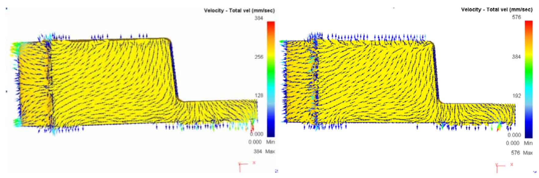
As shown in Figure 2, the velocity field distribution in the blank forming process of scheme 2 is shown. Figure a shows the upsetting stage. The axial flow velocity of the metal near the upper punch is large, and the axial velocity of the metal near the lower punch is 0, which is transformed into radial flow into the die cavity. In the second stage, the upper upsetting die stops moving, and the lower extrusion die moves downward. As shown in Fig. B, because the connecting skin is at the bottom and far from the upper angular gap, the filling speeds of the upper and lower parts are different. As shown in Fig. C, the metal radial flow speed near the lower punch is large, and the filling speed of the lower tooth cavity is faster than that of the upper tooth cavity. At the end of warm forging, as shown in Figure D, the free flow speed of metal is very small, and the upper and lower angular gaps are completely filled.

(b) Extrusion stage

(d) Warm forging end
As shown in Fig. 3, the distribution of blank velocity field in the forming process of scheme 3 is shown. As shown in Fig. a, the upper upsetting die and the upper extrusion die move downward to form upsetting. The axial speed decreases gradually from top to bottom, and the axial flow is gradually transformed into radial flow. At this time, it is conducive to the filling of the lower tooth cavity. The second stage is that the upper upsetting die stops moving, and the blank flows to the tooth cavity under the action of the upper and lower extrusion dies. As shown in Figure B, the metal flows evenly and symmetrically about the middle surface. The last stage is to fill the upper and lower top corners of the tooth cavity. As shown in Figure C, the middle surface of the tooth shape contacts the die first, and the upper and lower corners of the tooth shape are filled at the same time. Due to the rapid filling of the lower corners in the upsetting stage, the stroke in this stage is short, and the filling degree of the upper and lower corners is not different. At the end of forging, as shown in Figure D, the tooth cavity is completely filled.

(b) Bidirectional extrusion stage

(d) Warm forging end
Based on the analysis results of the velocity field of the three component scheme, the upward flow of the metal blank in scheme 1 produces warpage and the metal flow is uneven. In scheme 2 and scheme 3, the metal flows evenly, but in scheme 2, the connecting skin is at the bottom. When filling the upper top corner, the metal flow distance is long, the resistance is large, and it is easy to be filled. In the scheme, the three connecting skins are in the middle, the metal flow distance is short, the flow resistance is small, and the forming effect is good.