
As a high-precision speed reduction device critical for modern industrial robots, the rotary vector reducer demands exceptional transmission accuracy, with permissible angular transmission error often required to be less than one arc-minute. This stringent requirement makes the analysis of factors influencing its transmission precision a focal point of research. The secondary reduction stage, primarily comprising the cycloid gear, crankshafts, and the output mechanism (typically the planet carrier), is particularly significant. Errors originating from the manufacturing and assembly of these components severely impact the overall kinematic accuracy of the rotary vector reducer. This analysis aims to establish a theoretical model to quantify the influence of these primary errors, thereby providing guidance for design tolerance allocation and assembly process control.
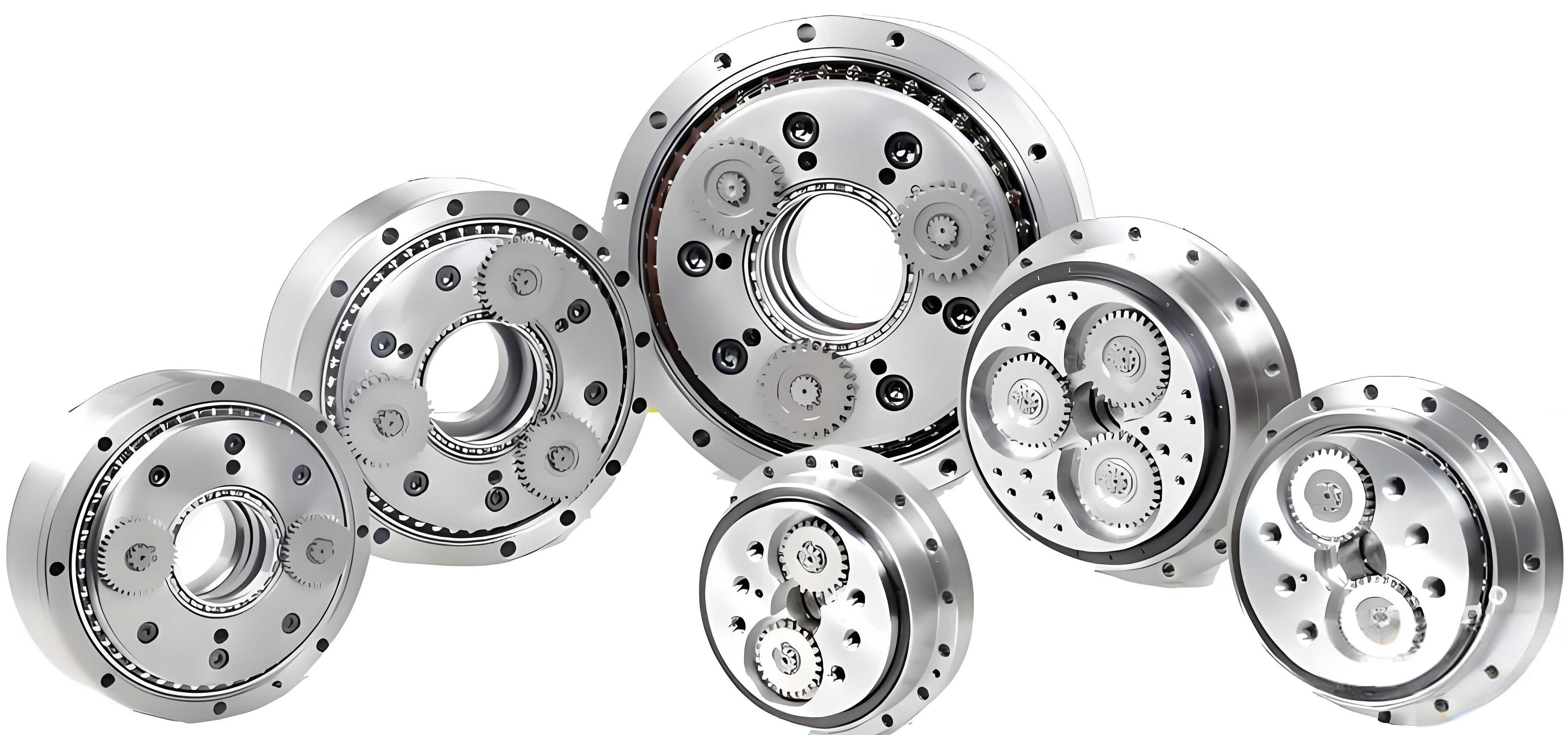
The secondary transmission stage of a standard rotary vector reducer operates on the principle of cycloidal motion. An input rotation is provided to two eccentric crankshafts, which are phase-shifted by 180 degrees. These crankshafts drive a pair of cycloid gears, which mesh with a stationary ring of needle rollers (the pinwheel). The oscillating rotation of the cycloid gears is then converted into a concentric output rotation through the output mechanism. The kinematic relationship between the crankshaft input and the final output is thus governed by the geometry of the crankshaft eccentrics, the holes in the cycloid gears, and the corresponding holes in the output mechanism.
1. Theoretical Foundation: The Four-Bar Linkage Equivalent Model
A powerful method for analyzing the error propagation in this subsystem is to model it as a planar four-bar linkage. For a rotary vector reducer with two crankshafts, this model elegantly captures the interactions between the key components. Consider one crankshaft-cycloid-output assembly pair. The equivalent four-bar linkage is constructed as follows:
- Link l1 & l3 (Crankshaft Eccentricity): These represent the eccentric portion of the two crankshafts. Their lengths are equal to the nominal eccentric distance, \( e \).
- Link l2 (Cycloid Gear Center Distance): This link connects the centers of the two crankshaft holes within a single cycloid gear.
- Link l4 (Output Mechanism Center Distance): This fixed link represents the distance between the centers of the two crankshaft bearing bores in the output mechanism (planet carrier).
In an ideal, error-free rotary vector reducer, links l1 and l3 are parallel and equal in length, and links l2 and l4 are parallel and equal in length, forming a parallelogram \( O_1P_iP_jO_2 \). The input angle \( \beta_1 \) of link l1 directly relates to the output angle \( \beta_4 \) of link l4 (which is theoretically fixed but its effective position changes due to errors). The presence of errors alters the lengths and orientations of these links, breaking the perfect parallelogram and introducing transmission error.
The fundamental vector loop equation for the four-bar mechanism, considering actual lengths \( l’_i = l_i + \Delta l_i \) and angles \( \beta’_i = \beta_i + \Delta \beta_i \), is:
$$ \vec{l’}_1 + \vec{l’}_2 – \vec{l’}_3 = \vec{l’}_4 $$
Projecting this equation onto the x and y axes yields the scalar equations:
$$ (l_1 + \Delta l_1) \cos \beta’_1 + (l_2 + \Delta l_2) \cos \beta’_2 = (l_3 + \Delta l_3) \cos \beta’_3 + (l_4 + \Delta l_4) \cos \beta’_4 $$
$$ (l_1 + \Delta l_1) \sin \beta’_1 + (l_2 + \Delta l_2) \sin \beta’_2 = (l_3 + \Delta l_3) \sin \beta’_3 + (l_4 + \Delta l_4) \sin \beta’_4 $$
When the position error of the output mechanism is not considered in its angle (i.e., \( \beta_4 \) is a reference), and assuming small angular variations for link l2 (\( \sin \beta’_2 \approx \beta’_2 \), \( \cos \beta’_2 \approx 1 – (\beta’_2)^2/2 \)), these equations can be simplified and solved for the coupler angle \( \beta’_2 \), which is directly linked to the output rotation error. The solution takes the quadratic form:
$$ a(\beta’_2)^2 + b\beta’_2 + c = 0 $$
where the coefficients are functions of the actual link parameters and the input angle \( \beta’_1 \):
$$ a = l’_2 l’_4 – l’_1 l’_2 \cos \beta’_1 $$
$$ b = 2 l’_1 l’_2 \sin \beta’_1 $$
$$ c = (l’_1)^2 + (l’_2)^2 + (l’_4)^2 – (l’_3)^2 – 2l’_1 l’_4 \cos \beta’_1 + 2l’_1 l’_2 \cos \beta’_1 – 2l’_2 l’_4 $$
Furthermore, radial clearance in the journal bearings (between crankshaft and cycloid gear hole, and between crankshaft and output mechanism hole) introduces an additional displacement vector \( \Delta \vec{p} \) at each hinge joint:
$$ \Delta \vec{p} = P_i P’_i = \Delta p \cdot \vec{f}_p $$
where \( \Delta p \) is the radial clearance and \( \vec{f}_p \) is the unit vector in the direction of relative displacement. This clearance effectively modifies the connection points in the linkage model.
2. Error Analysis Methodology and Base Parameters
The analysis distinguishes between two types of errors:
- Rigid (Kinematic) Error: The angular output error arising solely from the dimensional and geometric deviations of components and assembly clearances, under a no-load condition.
- Elastic (Loaded) Error: The comprehensive angular output error that includes both the rigid error and the additional displacement caused by elastic deformations at the contact points and bearings under operational load.
For this study, we consider a representative rotary vector reducer model, RV-40E. Its key parameters for the secondary stage are summarized below:
| Parameter | Symbol | Value | Unit |
|---|---|---|---|
| Pinwheel Pitch Circle Diameter | \(d_p\) | 128.0 | mm |
| Pin (Needle) Roller Diameter | \(D_{rp}\) | 6.0 | mm |
| Number of Cycloid Gear Teeth | \(z_c\) | 39 | – |
| Number of Pinwheel Teeth | \(z_p\) | 40 | – |
| Crankshaft Eccentricity | \(e\) (l1, l3) | 1.3 | mm |
| Cycloid Gear Hole Center Distance | \(l_2\) | \(2e\) (Nominal) | mm |
| Output Mechanism Hole Center Distance | \(l_4\) | \(2e\) (Nominal) | mm |
The analysis will investigate the individual and combined effects of errors within a practical tolerance band of ±0.1 mm for dimensional errors. The nominal center distances \(l_2\) and \(l_4\) are theoretically \(2e\). The load condition for elastic error analysis is derived from the rated torque transmission of the rotary vector reducer, leading to significant contact forces \(F^t\) and \(F^r\) (tangential and radial) at the crankshaft-cycloid gear bearings.
3. Individual Component Error Influence
3.1 Crankshaft Eccentricity Error (\(\Delta l_1, \Delta l_3\))
Errors in the machining of the crankshaft eccentric sections directly alter the lengths of links \(l_1\) and \(l_3\). The rigid error model accounts for bearing clearances altering the effective positions of points \(P_i\) and \(P_j\). Under load, the contact forces cause elastic deformation vectors \(\vec{l}_{11}\) and \(\vec{l}_{33}\) at these joints, further modifying the effective lengths \(l”_1\) and \(l”_3\) according to the law of cosines:
$$ l”_1 = \sqrt{ (l’_1)^2 + l_{11}^2 – 2 l’_1 l_{11} \cos \theta_1 } $$
$$ l”_3 = \sqrt{ (l’_3)^2 + l_{33}^2 – 2 l’_3 l_{33} \cos \theta_3 } $$
Here, \( \theta_1 \) and \( \theta_3 \) are the angles between the rigid-error eccentric vector and the elastic deformation vector, determined by the direction of the bearing reaction forces. Analysis shows that the maximum rigid error occurs when the input angle \( \beta’_1 = 90^\circ \). The forces at this position are used to calculate \( \theta_1 \) and \( \theta_3 \).
The calculated output angular error for a variation of crankshaft eccentricity error from -0.1 mm to +0.1 mm is presented conceptually below:
| Eccentricity Error \(\Delta e\) (mm) | Rigid Error Range (deg) | Elastic Error Range (deg) | Trend on Accuracy |
|---|---|---|---|
| -0.1 to +0.1 | 0.0333° – 0.0389° | 0.0335° – 0.0390° | Accuracy improves with negative bias; degrades with positive bias. |
The elastic error is marginally larger than the rigid error. The key finding is that manufacturing the crankshaft eccentricity toward the lower limit of its tolerance (negative bias) enhances the transmission accuracy of the rotary vector reducer.
3.2 Cycloid Gear Crank Hole Eccentricity Error (\(\Delta l_2\))
This error refers to the deviation in the distance between the centers of the two crankshaft bores in the cycloid gear. It directly changes the length of link \(l_2\). Bearing clearances affect the connection points. The elastic analysis follows a similar pattern, with forces inducing deformations that alter the effective linkage geometry.
| Hole Distance Error \(\Delta l_2\) (mm) | Rigid Error Range (deg) | Elastic Error Range (deg) | Trend on Accuracy |
|---|---|---|---|
| -0.1 to +0.1 | 0.036058° – 0.036111° | 0.03618° – 0.03624° | Accuracy slightly improves across the tolerance band, with a very mild preference for negative bias. |
Interestingly, the presence of this error within the specified band can partially compensate for other errors, slightly improving accuracy. This indicates that the tolerance for this parameter in a rotary vector reducer can be relatively relaxed, and a slight negative bias is marginally beneficial.
3.3 Output Mechanism Crank Hole Eccentricity Error (\(\Delta l_4\))
This error changes the fixed distance \(l_4\) between the crankshaft bearing bores on the output mechanism. It is a critical parameter as it defines the fixed frame of the four-bar linkage.
| Hole Distance Error \(\Delta l_4\) (mm) | Rigid Error Range (deg) | Elastic Error Range (deg) | Trend on Accuracy |
|---|---|---|---|
| -0.1 to +0.1 | 0.036008° – 0.036123° | 0.038588° – 0.038706° | Accuracy decreases then slightly rises with negative bias; increases significantly with positive bias. |
The elastic error is substantially larger here due to the loaded deformation affecting the fixed link’s effective length. The analysis strongly suggests machining this center distance toward the upper limit of its tolerance (positive bias) to maximize the transmission accuracy of the rotary vector reducer.
4. Combined Error Influence and Synthesis
In practice, all errors coexist. Their combined effect is not merely additive but interactive, as captured by the four-bar model with multiple simultaneous parameter changes. Solving the model equations for combined error inputs reveals the interaction patterns.
4.1 Crankshaft and Cycloid Gear Errors Combined
The simultaneous variation of \(\Delta e\) and \(\Delta l_2\) shows a convex, step-like surface for the output error. The lowest error (highest accuracy) occurs when the crankshaft error is negative and the cycloid gear hole error is within its band, confirming the individual trends.
Range for \(\Delta e, \Delta l_2 \in [-0.1, 0.1]\) mm:
$$ \text{Rigid Error: } 0.0347^\circ \text{ to } 0.0375^\circ $$
$$ \text{Elastic Error: } 0.0355^\circ \text{ to } 0.0383^\circ $$
4.2 Crankshaft and Output Mechanism Errors Combined
The combination of \(\Delta e\) and \(\Delta l_4\) also produces a convex error surface. The optimal region for a rotary vector reducer is with negative crankshaft error and positive output mechanism error.
Range for \(\Delta e, \Delta l_4 \in [-0.1, 0.1]\) mm:
$$ \text{Rigid Error: } 0.0346^\circ \text{ to } 0.0375^\circ $$
$$ \text{Elastic Error: } 0.0354^\circ \text{ to } 0.0383^\circ $$
4.3 Cycloid Gear and Output Mechanism Errors Combined
This combination yields an error surface with a concave middle and raised edges. The highest accuracy is achieved when the errors are antagonistic: cycloid gear hole error at positive extreme and output mechanism error at negative extreme, or vice-versa. Since the output mechanism error should be positively biased for optimal performance, the logical choice is to select a negative bias for the cycloid gear hole error.
Range for \(\Delta l_2, \Delta l_4 \in [-0.1, 0.1]\) mm:
$$ \text{Rigid Error: } 0.0358^\circ \text{ to } 0.0362^\circ $$
$$ \text{Elastic Error: } 0.0384^\circ \text{ to } 0.0387^\circ $$
5. Summary of Design and Manufacturing Guidelines
Based on the comprehensive four-bar linkage analysis of the secondary stage, the following guidelines can be established to enhance the transmission accuracy of a rotary vector reducer:
- Tolerance Allocation Strategy: The analysis provides a quantitative basis for assigning asymmetric tolerance zones or targeting specific bias within symmetric zones for critical dimensions.
- Component Manufacturing Bias:
- Crankshaft Eccentricity: Machine toward the lower limit (negative bias) of its tolerance.
- Cycloid Gear Crank Hole Center Distance: Machine toward the lower limit (negative bias) of its tolerance.
- Output Mechanism Crank Hole Center Distance: Machine toward the upper limit (positive bias) of its tolerance.
This specific combination leverages the interactive nature of the errors to minimize the net kinematic output error.
- Bearing Clearance Control: While clearances provide a degree of error compensation, they are also a source of free play and significantly increase elastic error under load. Strict control of bearing internal clearance is crucial for high-precision rotary vector reducers.
- Elastic vs. Rigid Error: The loaded (elastic) transmission error is consistently and significantly higher than the unloaded (rigid) error. This underscores the importance of stiffness analysis and the use of high-stiffness components and bearings in the design of a rotary vector reducer to maintain accuracy under operational torque.
The four-bar linkage model serves as an effective and intuitive tool for analyzing the primary geometric errors in the complex secondary stage of a rotary vector reducer. It transforms physical deviations into quantifiable parameters in a classic mechanism, allowing for clear visualization and calculation of their compounded effect on the critical output rotation angle. The findings from this model-driven analysis offer actionable insights for precision manufacturing and selective assembly, ultimately contributing to the production of higher-performance rotary vector reducers for demanding robotic applications.