
The dynamic characteristics of cylindrical gears with elliptical arc tooth profiles play a critical role in minimizing vibration and noise under harsh operating conditions. This study investigates the relationship between geometric parameters, operational speeds, and transmission stability through kinematic and dynamic simulations. Three key factors—cutter radius, tooth width, and rotational speed—are systematically analyzed to quantify their effects on speed fluctuation coefficients.
1. Structural Features of Elliptical Arc Tooth Line Cylindrical Gears
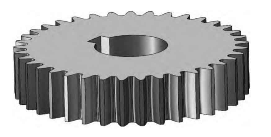
The unique elliptical arc tooth profile ensures full-line contact across the tooth width, enhancing load distribution compared to traditional spur gears. The intermediate cross-section features an involute profile, while adjacent sections rotate by a position angle relative to it. The elliptical tooth trace on the pitch cylinder satisfies:
$$
\begin{cases}
2a = \text{Major axis length} \\
2b = \text{Minor axis length} \\
b = a \cos \alpha
\end{cases}
$$
where \( \alpha \) denotes the pressure angle. This geometry guarantees uniform tooth thickness and pressure angle across all radial sections, as illustrated below:
2. Dynamic Model Formulation
The speed fluctuation coefficient \( \delta \) quantifies transmission stability:
$$
\delta = \frac{\omega_{\text{max}} – \omega_{\text{min}}}{\omega_m}
$$
where \( \omega_{\text{max}} \), \( \omega_{\text{min}} \), and \( \omega_m \) represent maximum, minimum, and average angular velocities. ADAMS simulations modeled gear pairs with parameters in Table 1.
| Parameter | Value |
|---|---|
| Module (mm) | 4 |
| Pressure Angle (°) | 20 |
| Driving Gear Teeth | 32 |
| Driven Gear Teeth | 80 |
| Material | Steel (E=207 GPa, ν=0.29) |
3. Cutter Radius Influence on Speed Fluctuation
Simulations evaluated 18 cutter radii (30–200 mm) while maintaining 60 mm tooth width and 3,500°/s input speed. Results demonstrate non-linear relationships between cutter radius and stability:
| RT (mm) | ω_max (°/s) | ω_min (°/s) | δ |
|---|---|---|---|
| 40 | 1,416.26 | 1,386.39 | 0.0213 |
| 80 | 1,405.93 | 1,395.79 | 0.0072 |
| 120 | 1,404.68 | 1,395.93 | 0.0062 |
| 160 | 1,413.52 | 1,389.25 | 0.0173 |
The optimal stability occurs when:
$$
1.34b \leq R_T \leq 2.34b
$$
where \( b \) represents tooth width. Excessive \( R_T \) reduces effective contact length, while insufficient values induce asymmetric stiffness distribution.
4. Tooth Width Optimization
Simulations with fixed \( R_T = 100 \) mm revealed distinct stability regimes based on tooth width \( b \):
| b (mm) | ω_max (°/s) | ω_min (°/s) | δ |
|---|---|---|---|
| 40 | 1,409.13 | 1,391.60 | 0.0125 |
| 60 | 1,402.50 | 1,398.31 | 0.0030 |
| 80 | 1,402.26 | 1,398.71 | 0.0025 |
| 100 | 1,408.27 | 1,394.40 | 0.0099 |
Minimum fluctuation occurs at:
$$
0.6R_T \leq b \leq 0.8R_T
$$
Narrow teeth approximate spur gear behavior, while excessive widths create stiffness discontinuities at tooth ends.
5. Rotational Speed Effects
Dynamic simulations across 2,500–7,500°/s input speeds revealed inverse correlation between speed and fluctuation:
| Input (°/s) | Output ω_max (°/s) | Output ω_min (°/s) | δ |
|---|---|---|---|
| 2,500 | 1,013.65 | 1,000.17 | 0.0135 |
| 5,500 | 2,209.83 | 2,196.90 | 0.0059 |
| 7,500 | 3,004.76 | 2,992.65 | 0.0040 |
The fluctuation coefficient follows:
$$
\delta \propto \frac{1}{\sqrt{n}}
$$
where \( n \) denotes input speed. Higher speeds enhance stability through reduced relative impact velocities and improved lubrication.
6. Experimental Validation
Prototype testing confirmed simulation predictions. Using PLC-based speed measurement, experimental δ values showed <5% deviation from ADAMS results:
| Speed (°/s) | Simulated δ | Experimental δ |
|---|---|---|
| 857 | 0.0077 | 0.0071±0.0003 |
| 2,123 | 0.0033 | 0.0031±0.0002 |
7. Conclusion
For cylindrical gears with elliptical arc tooth profiles:
- Optimal cutter radius satisfies \( 1.34b \leq R_T \leq 2.34b \)
- Tooth width should maintain \( 0.6R_T \leq b \leq 0.8R_T \)
- Speed fluctuation decreases with \( \delta \propto n^{-0.5} \)
These guidelines enable designers to optimize cylindrical gear performance for high-speed applications while minimizing vibrational energy losses.