
In my investigation of heavy-duty industrial machinery, I have often encountered premature failures in gear systems, particularly in spiral bevel gears used in rolling mills. These gears are critical for transmitting power between non-parallel shafts, and their failure can lead to significant downtime and economic losses. This study focuses on the analysis of tooth surface damage in spiral bevel gears installed in a ●650 billet continuous mill. The primary goal is to identify the root causes of the damage, validate the findings through theoretical and experimental means, and propose effective mitigation strategies. Spiral bevel gears, with their curved teeth, offer smooth and efficient torque transmission but are susceptible to surface failures under excessive loads. Understanding the mechanisms behind such damage is essential for improving gear design and maintenance practices.
The ●650 billet continuous mill, a key piece of equipment in steel production, utilizes spiral bevel gears in its drive systems. These gears are subjected to high torque and cyclic loading, making them prone to surface degradation. In this analysis, I will detail the operational context, describe the observed damage patterns, present measured data, and apply fatigue theory to explain the phenomena. Throughout this article, the term ‘spiral bevel gear’ will be emphasized repeatedly to underscore its centrality to the discussion. Additionally, I will incorporate tables and mathematical formulations to summarize key parameters and calculations, enhancing the clarity and depth of the analysis.
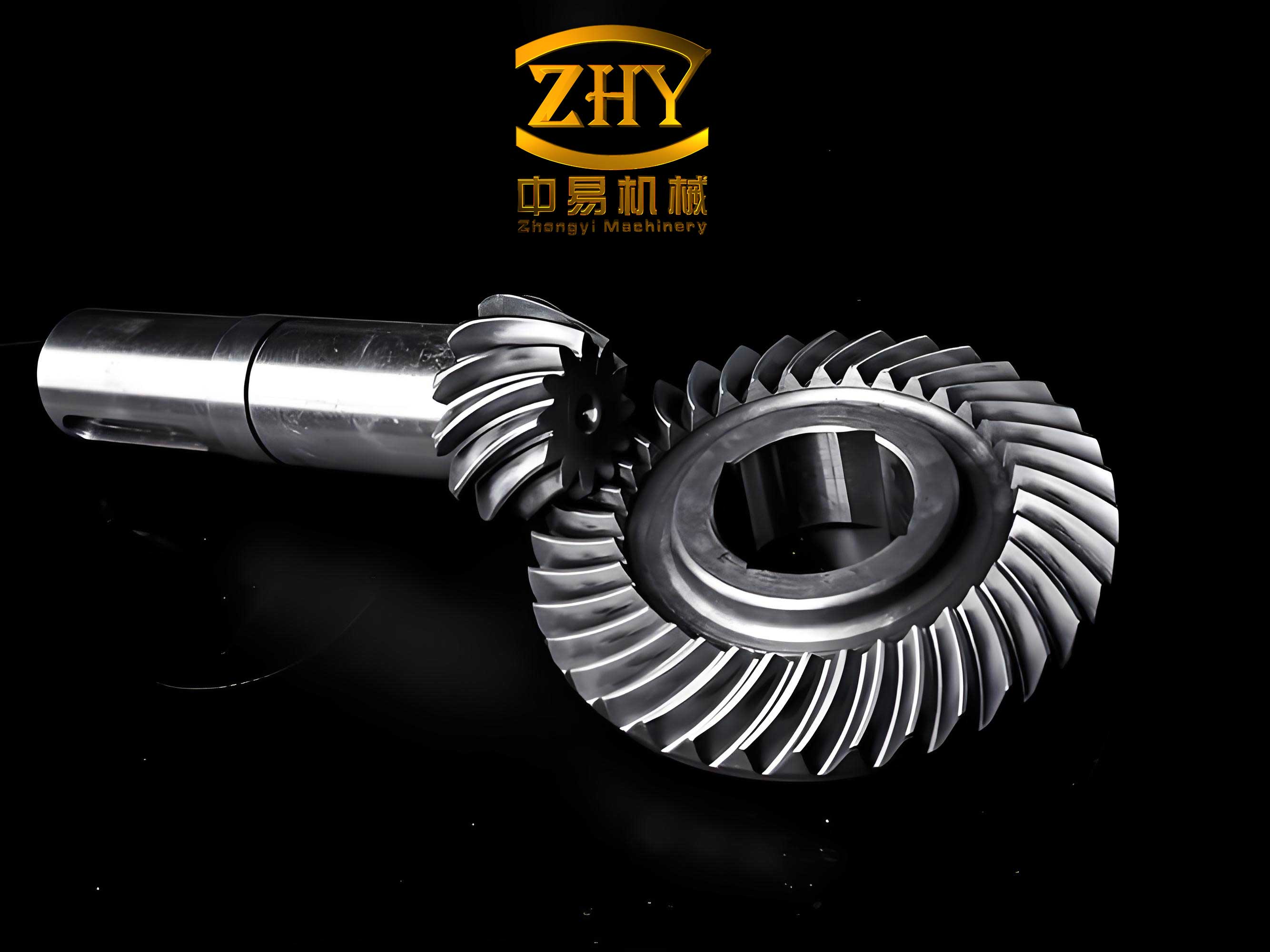
To begin, let me outline the structure of this study. First, I provide an overview of the mill’s equipment and the specifications of the spiral bevel gears involved. Next, I describe the characteristic features of the tooth surface damage observed in the field. Following that, I present the results of torque measurements taken during various rolling operations. Then, I conduct a comparative calculation of the contact strength for the spiral bevel gears, using established fatigue theories. Based on these calculations, I verify the causes of the damage and discuss the implications. Finally, I propose practical measures to delay the onset of such damage, offering recommendations for design modifications and operational improvements. This comprehensive approach ensures a thorough understanding of the failure mechanisms and aids in developing more resilient gear systems.
Equipment Overview and Spiral Bevel Gear Specifications
The ●650 billet continuous mill is a six-stand horizontal rolling mill designed for producing billets and slabs. It is driven by a centralized AC induction motor with a power rating of 40000 kW and a speed of 248 rpm. Each stand of the mill incorporates a reduction gearbox that uses spiral bevel gears to transmit torque from the motor to the rolls. These spiral bevel gears are manufactured according to the Gleason system, which is widely recognized for its precision in bevel gear production. The gears operate under severe conditions, including high loads and intermittent shocks, making their performance critical to mill productivity.
The design parameters of the spiral bevel gears vary across the six stands, reflecting differences in torque requirements. Below, I summarize the key parameters in a table to provide a clear comparison. The materials, hardness, and allowable torque values are essential for assessing their strength and durability.
| Parameter | Stand 1 & 4 | Stand 2 & 5 | Stand 3 & 6 |
|---|---|---|---|
| Pinion Teeth Number | 36 | 48 | 64 |
| Gear Teeth Number | 68 | 67 | 70 |
| Module (mm) | 36 | 36 | 34 |
| Material | 35CrMo | 35CrMo | 35CrMo |
| Tooth Surface Hardness (HB) | 260 | 240 | 260 |
| Allowable Maximum Torque (kNm) | 450 | 300 | 450 |
From this table, it is evident that the spiral bevel gears in stands 1 and 4 are designed for higher torque capacity compared to others. However, as I will show later, the actual operational torques often exceed these design limits, leading to accelerated damage. The material 35CrMo is a chromium-molybdenum alloy steel commonly used for high-strength gears, but its performance depends heavily on heat treatment and hardness levels. The spiral bevel gear’s tooth geometry, characterized by curved teeth and a specific pressure angle, influences the contact stress distribution and thus its susceptibility to surface failures.
Characteristics and Causes of Tooth Surface Damage
Upon inspecting the spiral bevel gears after approximately six months of operation, I observed widespread tooth surface damage, primarily in the form of pitting and ridging. The damage was most severe in the first and second stands, consistent with higher torque loads in these positions. The pitting appeared as numerous small pits or craters on the tooth surfaces, often concentrated near the pitch line where contact stresses are highest. These pits varied in size and shape, with many exhibiting扇贝壳 or扇形 patterns, indicative of progressive pitting. Additionally, ridging—characterized by elongated ridges along the sliding direction—was visible near the tooth tips, suggesting plastic deformation due to excessive pressure and sliding friction.
Based on the morphology of the damage, I identified it as progressive pitting combined with surface ridging, which is typical for low- to medium-speed heavy-duty spiral bevel gears. The primary factors contributing to such damage include overload conditions, material properties, surface hardness, and lubrication quality. In this case, after ruling out installation errors (which usually cause localized pitting) and poor lubrication (which often leads to scuffing or welding), I concluded that the root cause was excessive contact stress from operational loads beyond the design capacity. Furthermore, the relatively low surface hardness of the spiral bevel gears exacerbated the problem, allowing pitting to initiate earlier than expected.
To quantify the damage, I note that pitting initiates when the subsurface shear stress exceeds the material’s endurance limit. The contact stress on a spiral bevel gear tooth can be expressed using the Hertzian contact theory. For two curved surfaces in contact, the maximum contact pressure \( p_{\text{max}} \) is given by:
$$ p_{\text{max}} = \sqrt{\frac{F E^*}{\pi R^*}} $$
where \( F \) is the normal load per unit width, \( E^* \) is the equivalent Young’s modulus, and \( R^* \) is the equivalent radius of curvature. For spiral bevel gears, these parameters depend on the gear geometry and operating conditions. Excessive \( p_{\text{max}} \) leads to plastic deformation and fatigue cracks, resulting in pitting. The ridging phenomenon, on the other hand, is associated with adhesive wear and surface flow under high pressure, often described by the plastic strain accumulation model.
Measurement of Operational Torque Parameters
To validate the hypothesis of overloading, I conducted torque measurements on the mill during various rolling operations. The tests covered three typical working conditions: rolling of 90 mm square billets, 190 mm square billets, and plate blanks, using different steel grades such as BY2F, BY3F, 45 steel, and U74. The measured torque values for each stand are summarized in the table below. These data provide insight into the actual loads experienced by the spiral bevel gears during production.
| Billet Specification (mm×mm) | Steel Grade | Torque Type | Stand 1 | Stand 2 | Stand 3 | Stand 4 | Stand 5 | Stand 6 |
|---|---|---|---|---|---|---|---|---|
| 90×90 | BY3F | Maximum | 900 | 1060 | 600 | 300 | 220 | 200 |
| Average | 540 | 650 | 480 | 230 | 180 | 160 | ||
| BY2F | Maximum | 690 | 460 | 490 | 540 | 400 | 360 | |
| Average | 460 | 310 | 350 | 240 | 170 | 150 | ||
| 123×212 | BY3F | Maximum | 530 | 460 | 480 | – | 360 | – |
| Average | 350 | 270 | 370 | – | 230 | – | ||
| BY2F | Maximum | 730 | – | 460 | 380 | – | 290 | |
| Average | 440 | – | 360 | 290 | – | 180 | ||
| 190×190 | 45 Steel | Maximum | 1210 | 660 | 730 | – | 570 | 360 |
| Average | 580 | 450 | 490 | – | 370 | 300 | ||
| U74 | Maximum | 660 | 380 | 580 | – | – | – | |
| Average | 380 | 280 | 350 | – | – | – |
From this table, it is clear that the actual torques, especially in stands 1 and 2, frequently exceed the design allowable values of 450 kNm and 300 kNm, respectively. For instance, during rolling of 90 mm billets of BY3F, the maximum torque in stand 2 reached 1060 kNm, which is more than double the design limit. The average torques also surpass the design values in many cases, indicating sustained overloading. This overloading aligns with the observed severe damage in the first two stands of the spiral bevel gear system. The data confirm that the mill is operating beyond its original design capacity, leading to elevated contact stresses on the spiral bevel gear teeth.
Theoretical Analysis of Contact Strength Using Comparative Calculation
To further verify the damage causes, I performed a comparative calculation of the contact strength for the spiral bevel gears. This method, known as the comparative calculation approach, allows for a straightforward assessment of strength margins by comparing torque values limited by different strength criteria. I introduce two parameters, \( R_1 \) and \( R_2 \), defined as follows:
$$ R_1 = \frac{T_{\text{Hlim}}}{T_{\text{H}}} $$
$$ R_2 = \frac{T_{\text{Hs}}}{T_{\text{H}}} $$
where \( T_{\text{Hlim}} \) is the torque limited by the minimum contact strength (based on fatigue极限), \( T_{\text{Hs}} \) is the torque limited by the original design contact strength, and \( T_{\text{H}} \) is the actual operational torque. If \( R_1 \) or \( R_2 \) is greater than the minimum safety factor \( S_{\text{Hlim}} \), the gear has a low probability of damage within its design life; conversely, values below \( S_{\text{Hlim}} \) indicate high risk.
For spiral bevel gears, \( T_{\text{Hlim}} \) can be calculated using the Gleason strength formula, which accounts for geometry, material properties, and operating conditions. The expression is:
$$ T_{\text{Hlim}} \leq \frac{I b_{\text{cal}}}{K_A K_V K_{H\beta} Z_X Z_R} \cdot \frac{i d_{\text{el}}^2 \sigma_{\text{Hlim}}^2}{3000 Z_E^2} $$
where the symbols are defined in the table below:
| Symbol | Meaning |
|---|---|
| \( Z_E \) (N/mm²)¹/² | Material elasticity coefficient |
| \( K_A \) | Application factor |
| \( K_V \) | Dynamic factor |
| \( K_{H\beta} \) | Load distribution factor |
| \( b_{\text{cal}} \) (mm) | Calculated contact face width |
| \( \sigma_{\text{Hlim}} \) (N/mm²) | Contact fatigue limit stress |
| \( Z_X \) | Size factor |
| \( Z_R \) | Surface roughness factor |
| \( i \) | Gear ratio |
| \( I \) | Geometry factor |
| \( d_{\text{el}} \) (mm) | Pinion outer pitch diameter |
| \( T_{\text{Hlim}} \) (Nm) | Torque limited by minimum contact strength |
In my calculations, I used the recommended values from Gleason standards for spiral bevel gears. The gear life was set at 10⁷ stress cycles, corresponding to approximately 12 months of operation for the first stand under three-shift working conditions. The minimum safety factor \( S_{\text{Hlim}} \) was taken as 1.25, as per industry norms. The actual torque \( T_{\text{H}} \) was selected as the larger average value from the measurements for each stand to represent worst-case scenarios.
The results of the comparative calculation are presented in the table below. These values provide a quantitative measure of the contact strength adequacy for each spiral bevel gear in the mill.
| Parameter | Stand 1 | Stand 2 | Stand 3 | Stand 4 | Stand 5 | Stand 6 |
|---|---|---|---|---|---|---|
| \( R_1 \) | 1.09 | 1.14 | 1.77 | 2.19 | 2.01 | 2.90 |
| \( R_2 \) | 0.78 | 0.69 | 0.92 | 1.03 | 0.81 | 1.01 |
From this table, I observe that all \( R_2 \) values are below the minimum safety factor of 1.25, indicating that the actual contact strength of the spiral bevel gears is lower than the original design strength. Moreover, for stands 1 and 2, \( R_1 \) values are also below 1.25, meaning that the contact strength is even insufficient relative to the minimum required strength. This confirms that overloading is the primary cause of the tooth surface damage. The spiral bevel gears in the first two stands are operating under conditions where the contact stresses exceed both the design and minimum allowable limits, leading to accelerated pitting and ridging.
Discussion of Results and Implications
The combination of measured torque data and theoretical calculations provides compelling evidence that the spiral bevel gear failures are due to excessive contact stresses from overloading. The \( R_1 \) and \( R_2 \) values quantitatively demonstrate the strength deficiencies, particularly in the initial stands of the mill. This aligns with the observed damage patterns, where stands 1 and 2 showed the most severe pitting. The spiral bevel gear’s tooth surface hardness, initially at HB 240-260, is insufficient to withstand the elevated stresses, contributing to early damage initiation.
To delve deeper, I consider the fatigue life model for spiral bevel gears. The number of cycles to pitting initiation \( N \) can be estimated using the stress-life approach:
$$ N = \left( \frac{\sigma_{\text{end}}}{\sigma_{\text{eq}}} \right)^m $$
where \( \sigma_{\text{end}} \) is the endurance limit of the material, \( \sigma_{\text{eq}} \) is the equivalent contact stress, and \( m \) is the fatigue exponent (typically around 6-9 for gear steels). For the spiral bevel gears in this mill, \( \sigma_{\text{eq}} \) increases with torque, reducing \( N \) and thus shortening the time to pitting. The actual operational torques, as measured, often double the design values, leading to a significant reduction in fatigue life. For instance, if torque doubles, stress increases proportionally, and \( N \) decreases by a factor of \( 2^m \), which could be as high as 64 for \( m=6 \). This explains why pitting appeared within just six months instead of the expected design life.
Furthermore, the ridging phenomenon can be analyzed using plastic deformation criteria. The von Mises stress \( \sigma_{\text{VM}} \) in the surface layer must exceed the yield strength \( \sigma_y \) for plastic flow to occur. For spiral bevel gears, the contact pressure and sliding friction combine to elevate \( \sigma_{\text{VM}} \). The condition for ridging can be expressed as:
$$ \sigma_{\text{VM}} = \sqrt{3J_2} \geq \sigma_y $$
where \( J_2 \) is the second invariant of the deviatoric stress tensor. Under overloading, this condition is met, leading to surface flow and ridge formation. This complements the pitting analysis, showing that both fatigue and plastic deformation mechanisms are active in the spiral bevel gear damage.
Proposed Measures to Delay Tooth Surface Damage
Based on my analysis, I propose several measures to mitigate the premature damage of spiral bevel gears in the ●650 continuous mill. These measures aim to reduce contact stresses, improve material resistance, or enhance operational conditions.
- Redesign of the Spiral Bevel Gear System: The most effective solution is to redesign the spiral bevel gears to match the current production loads. This involves recalculating the gear geometry, selecting higher-strength materials, and optimizing heat treatment processes. For instance, increasing the module or face width can lower contact pressures. The new design should ensure that the allowable torque exceeds the maximum measured values, with a safety margin above 1.25. While this requires significant investment, it guarantees long-term reliability and avoids frequent replacements.
- Enhancement of Surface Hardness: If a full redesign is not feasible due to constraints, improving the surface hardness of the existing spiral bevel gears can provide a substantial benefit. Research indicates that the contact strength-limited load capacity is approximately proportional to the square of hardness. Thus, increasing the surface hardness from HB 240-260 to HB 300 could raise the capacity by about 25%. This can be achieved through advanced heat treatment techniques such as carburizing or nitriding. For example, carburizing can produce a hard case depth of 0.5-1 mm, significantly improving pitting resistance. The modified gears could then endure loads for up to 12 months before damage initiation, extending service life.
- Optimization of Lubrication: Adding extreme pressure (EP) additives to the lubricant can reduce friction and wear on spiral bevel gear teeth. These additives form protective films that prevent metal-to-metal contact, lowering the risk of pitting and ridging. Regular oil analysis and filtration are also recommended to maintain lubricant quality. Proper lubrication ensures that the contact stresses are distributed more evenly, mitigating stress concentrations.
- Operational Adjustments: Implementing load monitoring and control systems can help avoid peak overloads. By adjusting rolling parameters or scheduling maintenance based on torque data, the spiral bevel gears can operate within safer limits. Additionally, periodic inspections using non-destructive testing methods like vibration analysis or thermography can detect early signs of damage, allowing for timely interventions.
To quantify the potential improvement from hardness enhancement, I can use the relationship between hardness and contact fatigue limit. For many gear steels, \( \sigma_{\text{Hlim}} \) is roughly proportional to hardness \( H \). Thus, if hardness increases by a factor \( k \), the allowable torque increases by \( k^2 \). For example, raising hardness from HB 250 to HB 300 gives \( k = 300/250 = 1.2 \), so torque capacity increases by \( 1.2^2 = 1.44 \), or 44%. This would bring the \( R_2 \) values closer to or above the safety factor, reducing damage risk.
Conclusion
In this study, I have analyzed the tooth surface damage of spiral bevel gears in a ●650 billet continuous mill. Through detailed examination of damage characteristics, torque measurements, and theoretical strength calculations, I determined that the primary cause is overloading, leading to excessive contact stresses that exceed both the design and minimum strength limits of the gears. The comparative calculation method, using parameters \( R_1 \) and \( R_2 \), quantitatively confirmed that the spiral bevel gears, especially in the first two stands, operate with insufficient contact strength, resulting in progressive pitting and ridging within a short period.
The spiral bevel gear’s performance is critical to the mill’s operation, and addressing this issue requires a multifaceted approach. I have proposed measures such as redesigning the gear system, increasing surface hardness, improving lubrication, and implementing operational controls. Among these, enhancing hardness offers a cost-effective interim solution that can extend gear life significantly. Future work could involve finite element analysis to simulate stress distributions more accurately or experimental testing of prototype gears under accelerated conditions.
This analysis underscores the importance of regular monitoring and adaptive design in heavy-industrial applications. By understanding the failure mechanisms of spiral bevel gears, engineers can develop more robust systems that withstand the demands of modern production. The insights gained here are applicable not only to rolling mills but also to other machinery relying on spiral bevel gears for power transmission, contributing to broader advancements in gear technology and reliability engineering.