
Abstract: This comprehensive article delves into the world of spur gear, exploring their design principles, manufacturing techniques, and diverse applications. It begins with an overview of spur gear fundamentals, including their geometry and kinematics. The design section covers aspects such as gear tooth profiles, contact ratios, and the determination of key parameters like module and pressure angle. Manufacturing processes are then examined, highlighting traditional methods like hobbing and shaping, as well as modern advancements. The article further discusses the dynamic characteristics of spur gear, including load distribution, vibration analysis, and the effects of errors and tolerances. Applications across various industries, from automotive to aerospace, are presented, along with a look at future trends and challenges in spur gear technology.
1. Introduction
Spur gear is one of the most fundamental and widely used components in mechanical power transmission systems. They play a crucial role in converting rotational motion and torque between parallel shafts. The simplicity of their design, combined with their efficiency and reliability, has made them a staple in numerous industrial applications. Understanding the intricacies of spur gear, from their design and manufacturing to their performance in real-world applications, is essential for engineers and designers working in the field of mechanical engineering.
2. Fundamentals of Spur Gear
2.1 Geometry
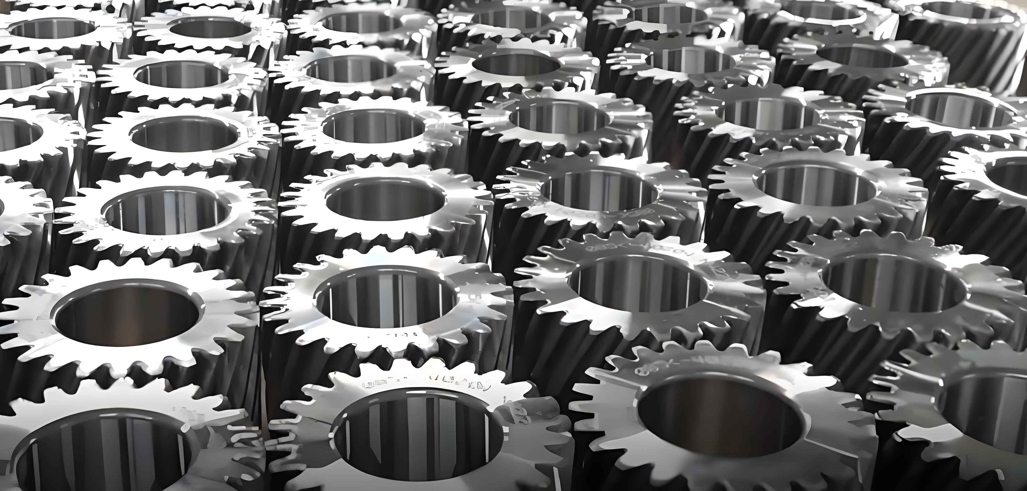
A spur gear consists of a cylindrical disk with teeth evenly spaced around its circumference. The key geometric parameters include the module (m), which is a measure of the size of the gear teeth and is defined as the ratio of the pitch diameter (d) to the number of teeth (z), i.e., . The pressure angle () is the angle between the line of action and the tangent to the pitch circle at the point of contact of the teeth. Common pressure angles are 14.5°, 20°, and 25°. The addendum (ha) is the height of the tooth above the pitch circle, and the dedendum (hf) is the depth of the tooth below the pitch circle. The total tooth height (h) is the sum of the addendum and dedendum, i.e., .
2.2 Kinematics
When two spur gear is in mesh, the rotational motion and torque are transmitted from the driving gear to the driven gear. The spur gear ratio (i) is defined as the ratio of the number of teeth on the driven gear (z2) to the number of teeth on the driving gear (z1), i.e., . The pitch line velocity (v) of spur gear is given by , where is the angular velocity and is the pitch radius. The meshing of the teeth occurs along the line of action, and the contact ratio (CR) is an important parameter that indicates the average number of teeth in contact during the meshing process. A higher contact ratio generally leads to smoother transmission and reduced vibration.
3. Design of Spur Gear
3.1 Tooth Profiles
The most common tooth profile used for spur gear is the involute profile. The involute curve is generated by unwrapping a string from a base circle. The involute tooth profile has several advantages, including a constant pressure angle during meshing, which results in a uniform distribution of load along the tooth surface. Other tooth profiles, such as cycloidal profiles, have also been used in certain applications, but the involute profile is predominant due to its simplicity and favorable kinematic properties.
3.2 Contact Ratio
The contact ratio is calculated as the ratio of the length of the path of contact to the base pitch. It is an important design parameter as it affects the load-carrying capacity and smoothness of transmission. A contact ratio of at least 1.2 is generally recommended for good performance. To increase the contact ratio, various methods can be employed, such as increasing the addendum modification or using spur gear with a higher number of teeth.
3.3 Determination of Key Parameters
The selection of key parameters such as module, pressure angle, and number of teeth is crucial in the design of spur gear. The module is chosen based on the required torque and speed of the application, as well as the available space. A larger module generally results in stronger teeth but may require a larger gear size. The pressure angle affects the force distribution on the tooth surface and is selected based on the load and speed requirements. The number of teeth is determined considering the gear ratio and the desired contact ratio.
4. Manufacturing of Spur Gear
4.1 Traditional Methods
4.1.1 Hobbing
Hobbing is a widely used manufacturing method for spur gear. In hobbing, a hob, which is a cylindrical cutter with helical teeth, is rotated and fed into the gear blank. The hob cuts the teeth on the blank as it rotates, producing the desired tooth profile. Hobbing is a highly efficient process and can produce gear with high accuracy.
4.1.2 Shaping
Shaping is another traditional method for manufacturing spur gear. In shaping, a cutting tool with a reciprocating motion is used to cut the teeth on spur gear blank. The shaping process is suitable for producing gears with small quantities or for spur gear with complex tooth profiles that are difficult to produce by hobbing.
4.2 Modern Advancements
4.2.1 Gear Grinding
Gear grinding is a precision manufacturing process that is used to improve the surface finish and accuracy of spur gear. In gear grinding, a grinding wheel is used to remove a small amount of material from the tooth surface, resulting in a smooth and accurate tooth profile. Gear grinding is often used for high-precision applications where tight tolerances are required.
4.2.2 Additive Manufacturing
Additive manufacturing, also known as 3D printing, is an emerging technology that has the potential to revolutionize the manufacturing of spur gear. In additive manufacturing, the gear is built layer by layer using a powdered material and a laser or other energy source. This process allows for the production of complex geometries and customized spur gear with reduced lead times and costs.
5. Dynamic Characteristics of Spur Gear
5.1 Load Distribution
The load distribution on the teeth of a spur gear is an important factor in determining its performance and durability. During meshing, the load is distributed along the line of action and is affected by factors such as the contact ratio, tooth profile, and manufacturing errors. Uneven load distribution can lead to premature wear and failure of the teeth. To ensure a uniform load distribution, proper design and manufacturing techniques are required, such as using gears with a high contact ratio and accurate tooth profiles.
5.2 Vibration Analysis
Vibration is a common problem in spur gear systems and can lead to noise, reduced efficiency, and premature failure. The sources of vibration in spur gear include meshing stiffness variations, manufacturing errors, and dynamic loads. To analyze the vibration of spur gear, various methods can be used, such as finite element analysis (FEA) and experimental modal analysis (EMA). These methods can help identify the sources of vibration and develop strategies to reduce it.
5.3 Effects of Errors and Tolerances
Manufacturing errors and tolerances can have a significant impact on the performance of spur gear. Errors such as tooth profile errors, pitch errors, and concentricity errors can lead to uneven load distribution, increased vibration, and reduced efficiency. To minimize the effects of errors and tolerances, strict quality control measures are required during the manufacturing process. This includes using accurate measuring instruments and following standardized manufacturing procedures.
6. Applications of Spur Gear
6.1 Automotive Industry
Spur gear is widely used in the automotive industry for various applications, such as in the transmission system, engine timing system, and differential. In the transmission system, spur gear is used to change the speed and torque of the vehicle. In the engine timing system, spur gear is used to synchronize the movement of the camshaft and crankshaft. In the differential, spur gear is used to distribute the torque between the wheels.
6.2 Aerospace Industry
In the aerospace industry, spur gear is used in applications such as in the engine accessory drive system and the landing gear actuation system. In the engine accessory drive system, spur gear is used to drive accessories such as generators, fuel pumps, and hydraulic pumps. In the landing gear actuation system, spur gears are used to actuate the landing gear up and down.
6.3 Industrial Machinery
Spur gear is also widely used in industrial machinery for various applications, such as in conveyors, pumps, and compressors. In conveyors, spur gear is used to drive the conveyor belt. In pumps, spur gear is used to drive the impeller. In compressors, spur gear is used to drive the compressor rotor.
7. Future Trends and Challenges
7.1 Trends
7.1.1 Miniaturization
With the increasing demand for smaller and more compact devices, there is a trend towards the miniaturization of spur gear. Miniaturized spur gear is required for applications such as in microelectromechanical systems (MEMS) and medical devices.
7.1.2 High-Speed and High-Power Applications
As technology advances, there is a growing need for spur gear that can operate at high speeds and handle high powers. This requires the development of new materials and manufacturing techniques to improve the strength and durability of spur gear.
7.2 Challenges
7.1.1 Precision Manufacturing
The demand for high-precision spur gear is increasing, especially for applications in aerospace and high-tech industries. However, achieving high precision in manufacturing is a challenge due to factors such as tool wear, material properties, and manufacturing errors.
7.1.2 Noise and Vibration Reduction
Noise and vibration are major concerns in spur gear applications. Reducing noise and vibration requires a comprehensive understanding of the sources of vibration and the development of effective strategies to mitigate them.
In conclusion, spur gear is an essential component in mechanical power transmission systems. Their design, manufacturing, and performance are crucial factors in determining the efficiency and reliability of the overall system. As technology continues to evolve, new trends and challenges will emerge, requiring continuous research and development to improve the performance of spur gear.