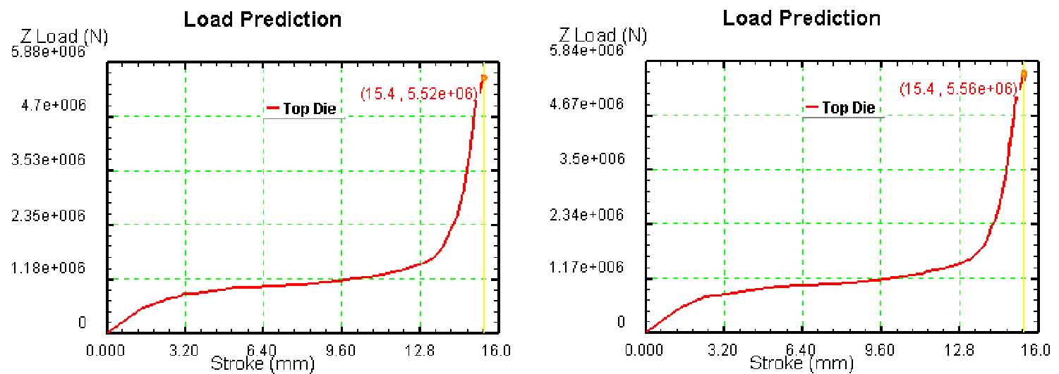
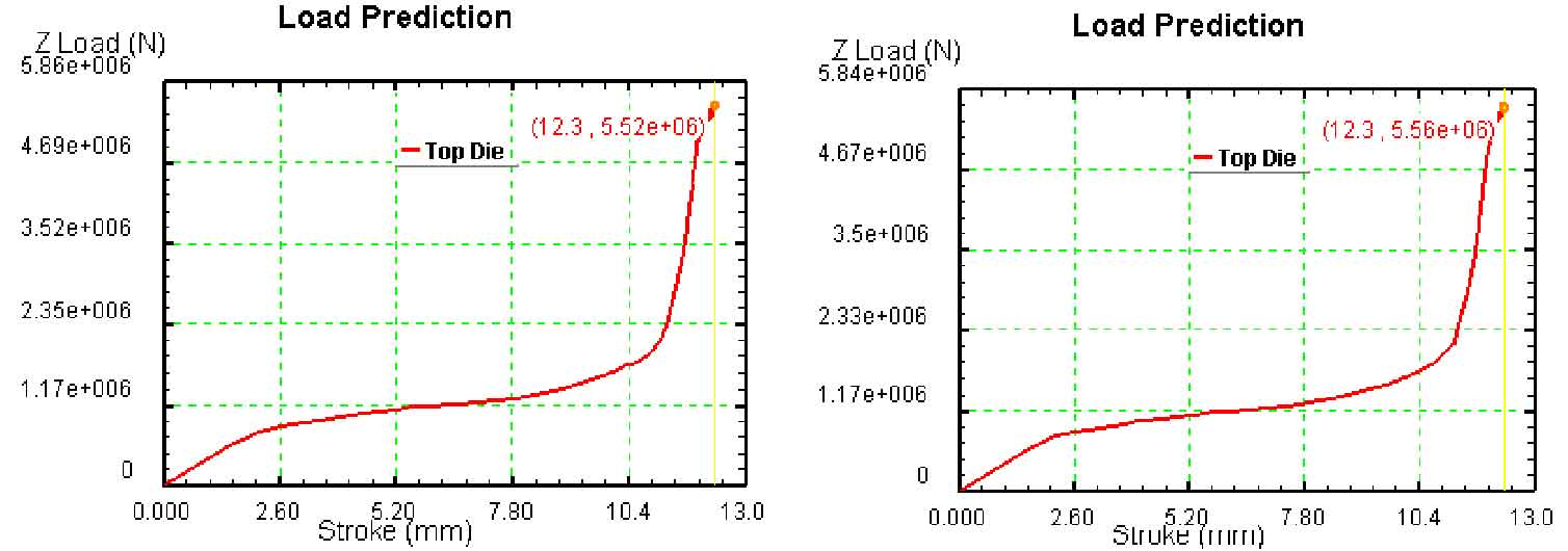
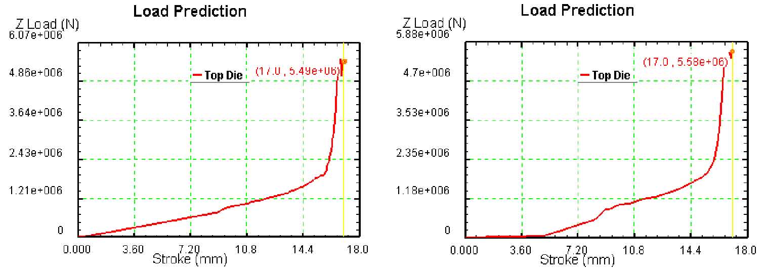
Different bevel gear die structures will directly affect the metal flow, thus affecting the load required in the forming process. As shown in the figure, the stroke load curves of bevel gear blanks of different sizes under different die structure schemes are shown, in which (a) and (b) are the stroke load curves of bevel gear blanks with outer diameter of 170 mm under two die structure schemes a and B respectively, (c) And (d) are the travel load curves of the blank with an outer diameter of 175 mm under two die structure schemes a and B respectively, (E) and (f) are the travel load curves of the blank with an outer diameter of 180 mm under two die structure schemes a and B respectively.

(b) Stroke load curve of scheme b with blank outer diameter of 170 mm

(d) Stroke load curve of scheme b with billet outer diameter of 175 mm

(f) Stroke load curve of scheme b with billet outer diameter of 180 mm
It can be seen from the figure that compared between figure (a) and figure (b), figure (c) and figure (d), and figure (E) and figure (f), the law of stroke load curve of the two different bevel gear die structure schemes is basically the same, and the maximum load of the two bevel gear die structures is not much different.
| Blank outer diameter (mm) | Maximum load (KN) scheme a | Maximum load (KN) scheme b |
| 170 | 5520 | 5560 |
| 175 | 5520 | 5560 |
| 180 | 5490 | 5580 |
The table shows the maximum load of bevel gear blanks of different sizes under the schemes of different die structures. It can be seen from the table that in general, the maximum load value of scheme B is slightly greater than that of scheme a.
