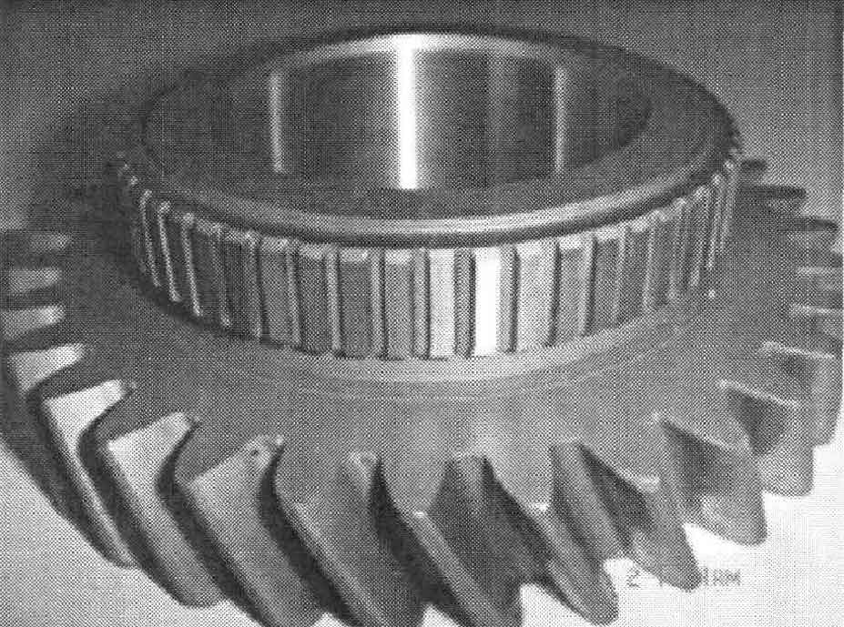
Figure 1 shows the helical cylindrical gear in the automobile gearbox. The normal surface modulus M = 2.5mm, the number of teeth z = 32, and the normal surface pressure angle α= 20 °, helix angle β= 25 °, normal tooth crest height coefficient h = 1, normal crest clearance coefficient C = 0.25, spiral cylindrical gear thickness H1 = 15mm, boss diameter d = 60mm, boss height h2 = 15mm, material 20crmn. The keyway and round hole on the boss of the helical cylindrical gear are processed after closed die forging.
The teeth of helical cylindrical gears have a helix angle β, The spiral cylindrical gear forging cannot be demoulded according to the ordinary ejection method after forming. The concave die of die forging helical cylindrical gear is designed as a bearing structure, which can rotate freely along the axis of helical cylindrical gear. When the ejector rod ejects the forging, the female die rotates automatically and the forging is demoulded.
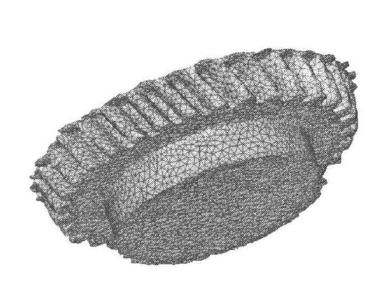
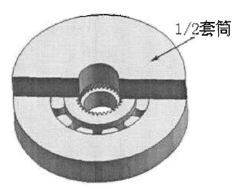
Due to the existence of tooth helix angle β, The concave die can not be designed as a floating concave die, the outer edge of the punch can not be designed as a tooth shape, and the parting surface can not be on the tooth. When the helical cylindrical gear is closed die forged without treatment, the forging is easy to produce flash at the parting surface. In the final forming stage of helical cylindrical gear, due to the generation of flash and the difficulty of filling at the tooth cavity, the metal does not flow to the tooth cavity, but flows to the flash, resulting in the failure of complete filling of the teeth, Fig. 2. A sleeve is placed above the female die, as shown in Figure 3. The sleeve restricts the metal, prevents flash during forging forming, and can not completely fill the tooth cavity. It can also guide the male die.