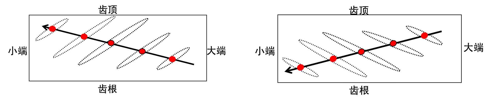
As shown in Figure 1, the change diagram of meshing footprint during the ideal meshing process of hypoid gear is shown. For the contact concave surface of hypoid gear, the change trend of meshing point is shown in the black line in Figure 1 (a). The hypoid gear enters the meshing from the big end near the tooth root, and exits the meshing at the small end near the tooth top, where the red origin is the contact center of the hypoid gear corresponding to a certain meshing position, Due to the elastic deformation between the contact tooth surfaces of the hypoid gear, a contact ellipse centered on the contact center will appear at any contact time. The long axis direction of the contact ellipse is from the tooth root of the small end of the hypoid gear to the tooth crest of the big end. The contact ellipse area is determined by the contact force. The greater the contact force, the greater the elastic deformation of the contact tooth surface, and the larger the contact ellipse area, and vice versa. The contact force of hypoid gear is small when entering and exiting meshing, so the corresponding contact area is small. In the middle position, the contact force of hypoid gear is large, and the contact ellipse area is also large. For the contact convex surface of hypoid gear, as shown in Figure 1 (b), different from the contact concave surface, the hypoid gear enters the meshing from the position where the big end is close to the tooth top, and exits the meshing at the position where the small end is close to the tooth root. The direction of the long axis of the contact ellipse is from the tooth top of the small end of the hypoid gear to the tooth root of the big end.
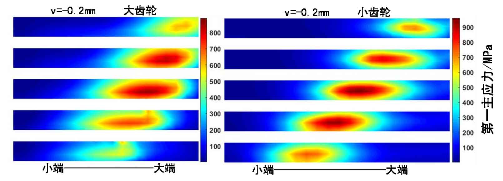
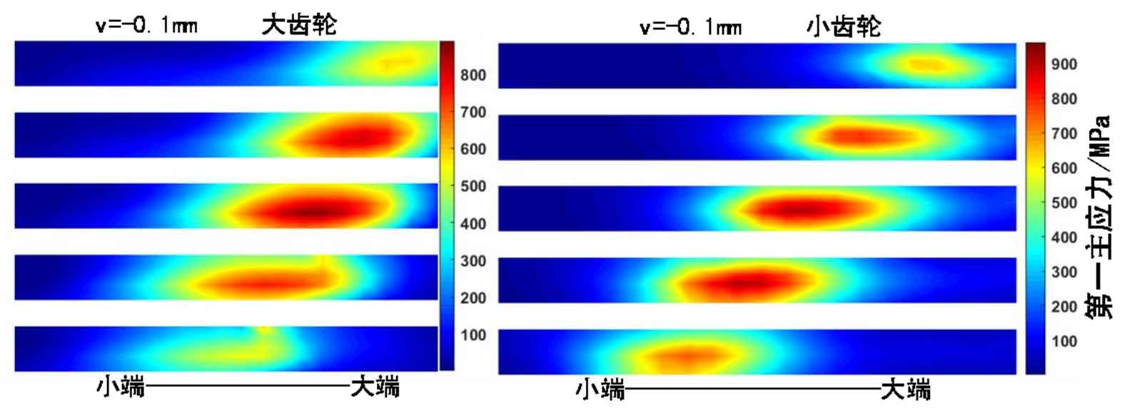
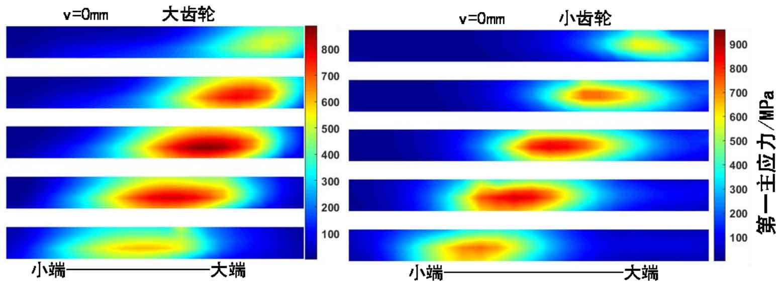
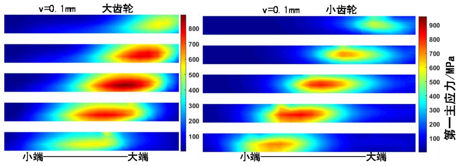
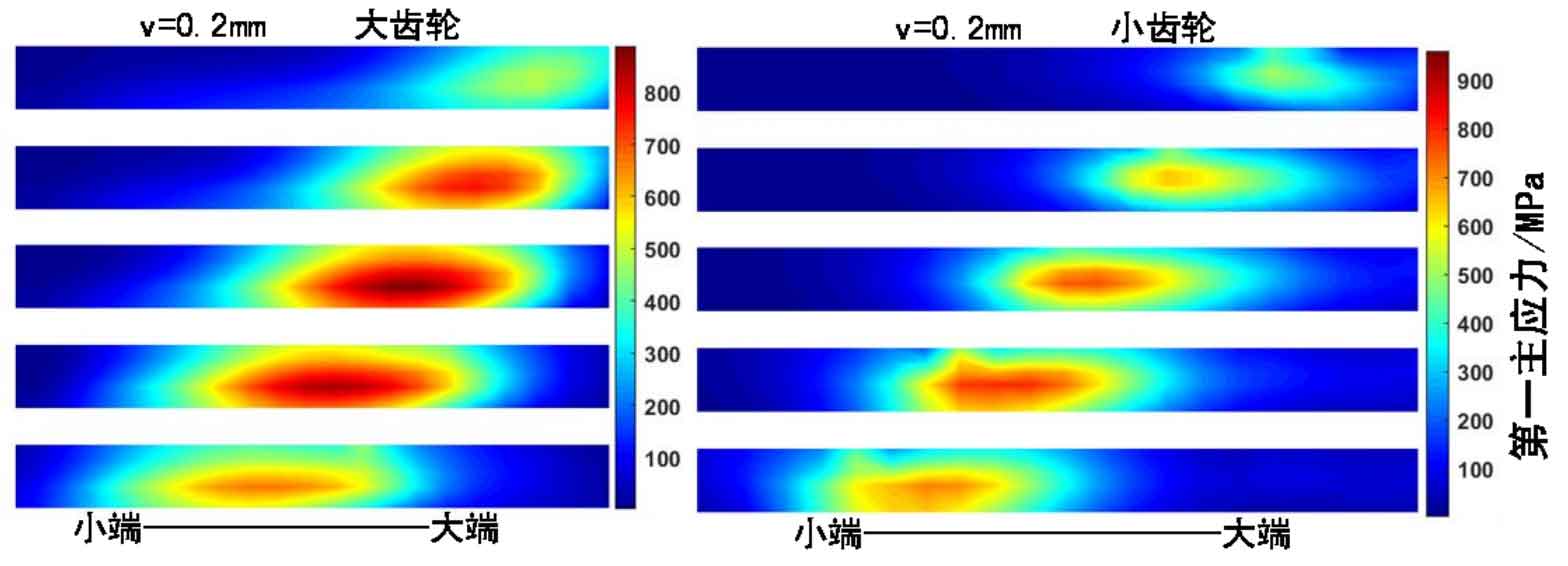
As shown in Figure 2, when the offset position deviation V of the pinion and pinion changes, the change trend of the tooth root bending stress is shown in the figure. From top to bottom, it is the corresponding hypoid tooth root stress change diagram when v=-0.2mm, -0.1mm, 0mm, 0.1mm, 0.2mm. The left side of the figure is the change of the tooth root bending stress of the big gear, and the right side is the change of the tooth root bending stress of the pinion. It can be seen that with the positive increase of V value, the position of the maximum principal stress of the gear root moves from the big end to the small end, and the maximum principal stress of the hypoid gear root also changes when entering and exiting the mesh.
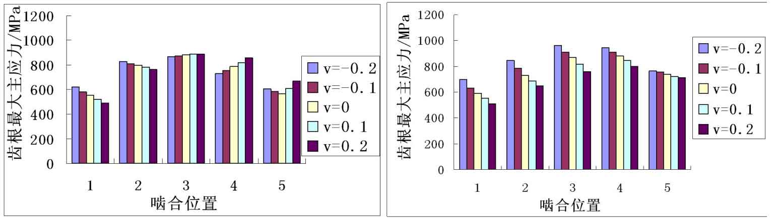
As shown in Figure 3, it is the maximum value of the first principal stress at the tooth root corresponding to the meshing position in Figure 2. When the value of V increases in a positive direction, the maximum value of the first principal stress corresponding to the root stress of the big gear decreases significantly when meshing in and increases significantly when meshing out, while the maximum value of the first principal stress corresponding to the root stress of the small gear decreases significantly when meshing in and changes little when meshing out. When the value of V increases in a negative direction, the maximum value of the first principal stress corresponding to the meshing of the pinion root increases significantly and changes little when meshing out, while the maximum value of the first principal stress of the gear root increases when meshing in and decreases when meshing out. From the above comparison, it can be seen that the installation deviation in direction V mainly causes the change of the position of the dangerous point and the change of the maximum principal stress at the dangerous point of the pinion and pinion, and the change of the root stress of the pinion and pinion to V is obvious.