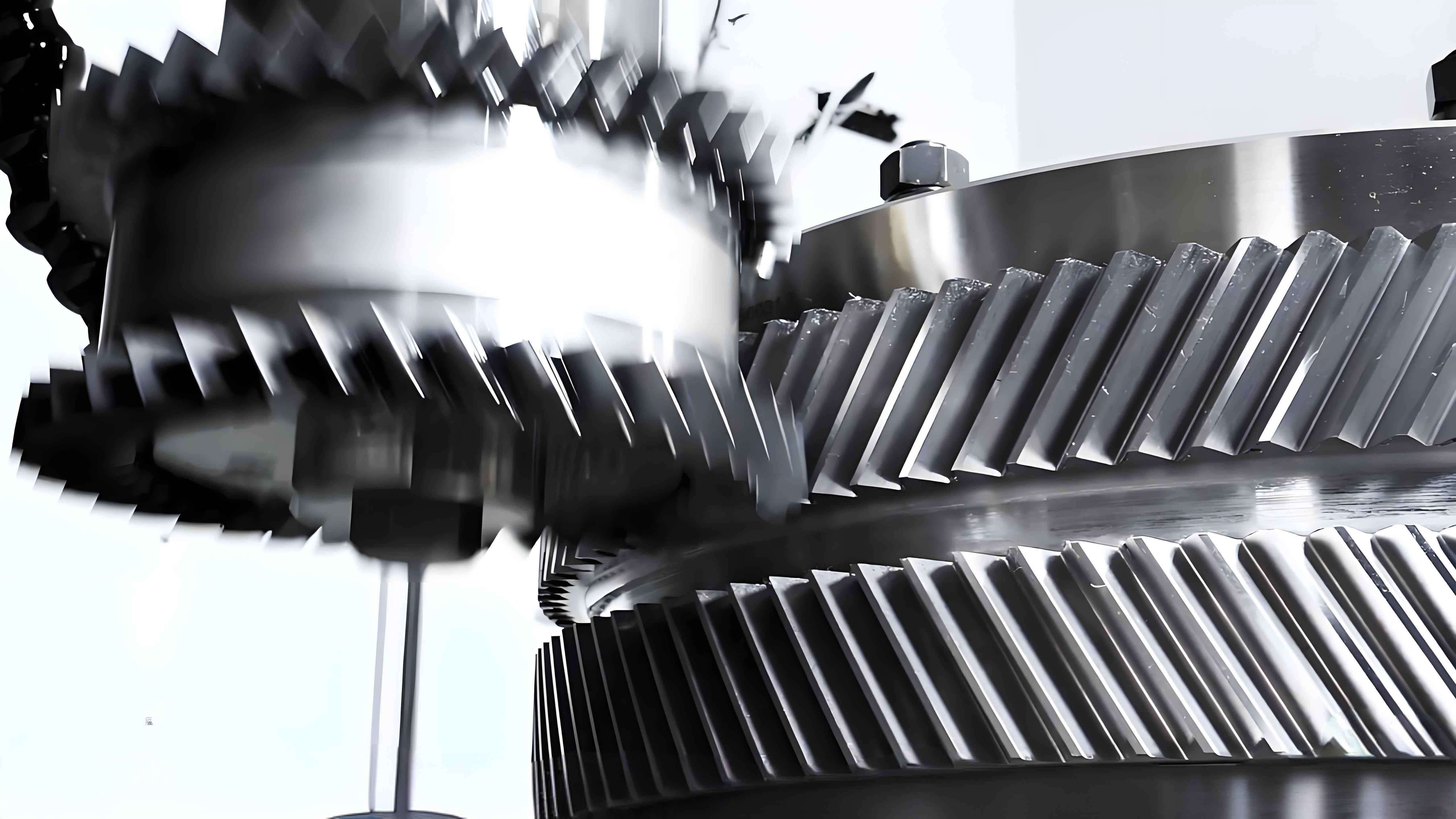
Herringbone gears are widely used in high-speed mechanical transmissions due to their superior load-bearing capacity and axial force cancellation. However, windage losses become significant at rotational speeds exceeding 50 m/s pitch line velocity. This paper investigates the aerodynamic characteristics and drag reduction strategies for herringbone gear systems using computational fluid dynamics (CFD) with dynamic mesh technology.

The governing equations for fluid dynamics analysis include:
Mass Conservation:
$$ \frac{\partial \rho}{\partial t} + \nabla \cdot (\rho \mathbf{v}) = 0 $$
Momentum Conservation:
$$ \frac{\partial (\rho u_i)}{\partial t} + \nabla \cdot (\rho u_i \mathbf{v}) = \nabla (\mu \nabla u_i) – \frac{\partial p}{\partial x_i} + S_i $$
Realizable k-ε Turbulence Model:
$$ \frac{\partial}{\partial t}(\rho k) + \frac{\partial}{\partial x_i}(\rho k u_i) = \frac{\partial}{\partial x_j}\left[\left(\mu + \frac{\mu_t}{\sigma_k}\right)\frac{\partial k}{\partial x_j}\right] + G_k + G_b – \rho \epsilon $$
$$ \frac{\partial}{\partial t}(\rho \epsilon) + \frac{\partial}{\partial x_i}(\rho \epsilon u_i) = \frac{\partial}{\partial x_j}\left[\left(\mu + \frac{\mu_t}{\sigma_\epsilon}\right)\frac{\partial \epsilon}{\partial x_j}\right] + \rho C_1 S \epsilon – \rho C_2 \frac{\epsilon^2}{k + \sqrt{\nu \epsilon}} $$
Key Findings:
The herringbone gear system demonstrates distinct airflow patterns during operation:
| Parameter | Value |
|---|---|
| Maximum Turbulent Kinetic Energy | 38.6 m²/s² |
| Pressure Differential at Mesh Zone | 12.4 kPa |
| Dominant Windage Source | Tooth Surface (92.7%) |
The windage power follows cubic relationship with rotational speed:
$$ P_w \propto n^3 $$
where $n$ represents rotational speed (rpm).
Drag Reduction Strategies:
| Strategy | Windage Reduction | Optimal Parameter |
|---|---|---|
| Windshield Coverage | 5.3% | 135° Coverage Angle |
| Baffle Installation | 3.5% | 8 mm Clearance |
| Oil Separator | 4.1% | 45° Installation Angle |
The moment of resistance on herringbone gear teeth shows periodic variation:
$$ T_c = \frac{1}{N} \sum_{i=1}^{N} \left( \int_{A} p \mathbf{r} \times d\mathbf{A} \right)_i $$
where $p$ = surface pressure, $\mathbf{r}$ = position vector, and $N$ = number of time steps.
Performance Optimization:
Optimal configuration for herringbone gear systems achieves:
| Parameter | Baseline | Optimized |
|---|---|---|
| Total Windage Power | 411.4 kW | 372.8 kW |
| System Efficiency | 96.2% | 97.8% |
| Pressure Fluctuation | ±18% | ±9% |
The comprehensive analysis demonstrates that proper implementation of aerodynamic optimization strategies can significantly improve the performance of herringbone gear systems in high-speed applications. Future research directions include multi-phase flow analysis and transient thermal coupling effects for enhanced prediction accuracy.
