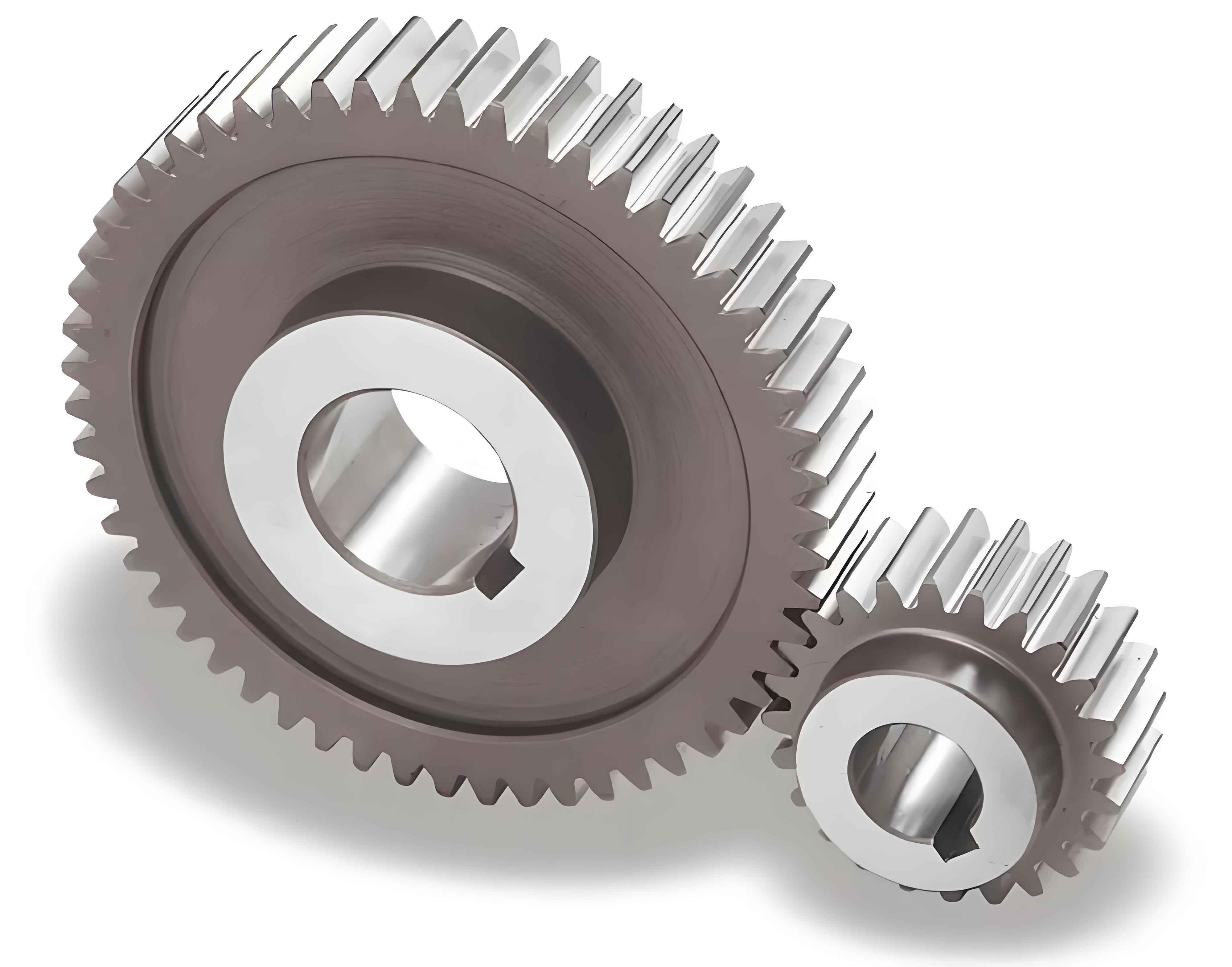
This paper presents a comprehensive analytical approach to determine the time-varying mesh stiffness of spur gear pairs considering tooth length modifications (TLM) and axial misalignment. The proposed method integrates elastic mechanics, tooth contact analysis (TCA), and loaded tooth contact analysis (LTCA) to address the nonlinear contact characteristics of spur gears under complex geometric deviations.

Mathematical Modeling of Geometric Deviations
The total tooth surface error for spur gears with crowning and misalignment is expressed as:
$$E_i = C_{ci}^{(p)} + C_{ci}^{(g)} + C_{mi}$$
Where:
$C_{ci}$ = Crowning modification at position $b_i$
$C_{mi}$ = Misalignment-induced deviation
The crowning profile follows a polynomial distribution:
$$C_{ci} = C_c \cdot \left(\frac{b_i – b_0}{B/2}\right)^s$$
Axial misalignment is calculated using:
$$C_{mi} = \frac{b_i}{\cos\beta_b} \cdot \left[(\theta_{x1}-\theta_{x2})\cos\psi_{12} + (\theta_{y1}-\theta_{y2})\sin\psi_{12}\right]$$
Stiffness Calculation Framework
The proposed stiffness model considers four primary components:
| Stiffness Component | Formula |
|---|---|
| Bending Stiffness | $\frac{1}{dK_b} = \int_0^{x_{ps}} \frac{3[(x_{ps}-x)\cos\alpha – h_{ps}\sin\alpha]^2}{2Eh_x^3db}dx$ |
| Shear Stiffness | $\frac{1}{dK_s} = \int_0^{x_{ps}} \frac{1.2\cos^2\alpha}{2Gh_xdb}dx$ |
| Axial Compression | $\frac{1}{dK_a} = \int_0^{x_{ps}} \frac{\sin^2\alpha}{2Eh_xdb}dx$ |
| Hertzian Contact | $dK_h = \frac{E_e^{0.9} \cdot db^{0.8} \cdot F_i^{0.1}}{1.275}$ |
Coupled Stiffness Analysis
The coupling effect between sliced tooth segments is modeled as:
$$K_{ci(i+1)} = \frac{2.75(dK_{ti} + dK_{t(i+1)})}{2} \cdot \left(\frac{db}{m}\right)^2$$
The total mesh stiffness for multi-tooth engagement considers foundation stiffness correction:
$$\frac{1}{K_{tf}} = \frac{1}{\lambda_p K_f^{(p)}} + \frac{1}{\lambda_g K_f^{(g)}}$$
Validation and Parametric Study
Key geometric parameters of test spur gears:
| Parameter | Pinion | Gear |
|---|---|---|
| Module (mm) | 2 | 2 |
| Teeth Count | 25 | 30 |
| Face Width (mm) | 20 | 20 |
| Pressure Angle | 20° | 20° |
The proposed method demonstrates 3% maximum error compared to FEM results. Variation of mesh stiffness with different misalignment angles shows:
$$K_{\text{mesh}} \propto \frac{1}{\theta_{\text{mis}}^{0.48}}$$
For crowning modifications (10-25μm), stiffness reduction follows:
$$\Delta K = 0.15C_c^{1.2} \text{ kN/mm}$$
Conclusion
This analytical framework enables accurate prediction of spur gear mesh stiffness considering manufacturing and assembly deviations. The slice-based approach with coupling effects provides superior accuracy (97% correlation with FEM) compared to conventional methods. The methodology serves as fundamental theory for optimizing spur gear modifications in power transmission systems.
