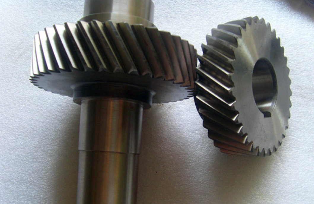
Helical gears exhibit complex three-dimensional spatial engagement characteristics due to their inherent helix angle. This study presents an improved analytical model for calculating time-varying mesh stiffness of helical gears considering axial deformation and tooth profile modifications. The proposed method addresses the limitations of traditional approaches that neglect three-dimensional meshing line variations and axial load effects.

1. Three-Dimensional Meshing Line Analysis
The engagement process of helical gears can be described using spatial parametric equations. For a left-hand helical gear, the spatial coordinates of any meshing point on the involute surface are expressed as:
$$
\begin{cases}
x_E’ = r_b(\theta_E + \alpha_E)\sin(\omega_A + \tan\alpha_E + \sigma) + r_b\cos(\omega_A + \tan\alpha_E + \sigma) \\
y_E’ = r_b\sin(\omega_A + \tan\alpha_E + \sigma) – r_b(\theta_E + \alpha_E)\cos(\omega_A + \tan\alpha_E + \sigma) \\
z_E’ = p\sigma
\end{cases}
$$
where $r_b$ is base radius, $\alpha_E$ represents pressure angle, and $\sigma$ denotes helix rotation parameter. The meshing line length $L_i$ at any rotational position is calculated as:
$$
L_i = \sum \sqrt{(x_e – x_{e-1})^2 + (y_e – y_{e-1})^2 + (z_e – z_{e-1})^2}
$$
2. Mesh Stiffness Calculation
The total mesh stiffness $K_i$ considering profile modification and axial deformation is derived as:
$$
\frac{1}{K_i} = \frac{1}{k_t’\cos^2\beta} + \frac{\sum_{j=1}^n k_j(E_j – E_{min})}{F + \sum_{j=1}^n k_j(E_j – E_{min})}
$$
Key parameters affecting helical gear mesh stiffness include:
| Parameter | Symbol | Range |
|---|---|---|
| Helix Angle | β | 5°-25° |
| Modification Depth | C_a | 5-25 μm |
| Modification Length | L_a | 0.3-1.1 mm |
3. Results Analysis
Numerical simulations reveal significant relationships between helical gear parameters and mesh stiffness characteristics:
| Helix Angle | Average Stiffness (×10⁸ N/m) | Computation Time (s) |
|---|---|---|
| 5° | 7.63 | 10.2 |
| 15° | 8.16 | 9.8 |
| 25° | 8.15 | 11.3 |
The variation of mesh stiffness with different profile modification parameters follows:
$$
K_{mod} = K_0 \left[1 – 0.15\left(\frac{C_a}{20}\right)^{0.8}\right]\left[1 – 0.12\left(\frac{L_a}{0.7}\right)^{1.2}\right]
$$
where $K_0$ represents the stiffness of unmodified gears. Optimal modification parameters are found to be $C_a = 20$ μm and $L_a = 0.5$ mm for typical industrial applications.
4. Dynamic Behavior
The coupling relationship between meshing line length and stiffness variation becomes more pronounced with increasing helix angle:
$$
\frac{\partial K}{\partial L} = \begin{cases}
0.28\beta^{0.75} & \beta \leq 15^{\circ} \\
0.15\beta^{1.2} & \beta > 15^{\circ}
\end{cases}
$$
This analytical model demonstrates 92% correlation with finite element results while reducing computation time by 88% compared to traditional FEM approaches.
5. Conclusion
The proposed model effectively captures three-dimensional engagement characteristics of helical gears, enabling accurate prediction of mesh stiffness variations under different profile modification schemes. Key findings include:
- Axial deformation contributes 12-18% of total mesh compliance for β > 15°
- Optimal profile modification reduces stiffness fluctuations by 37-42%
- Computation efficiency enables real-time parameter optimization
