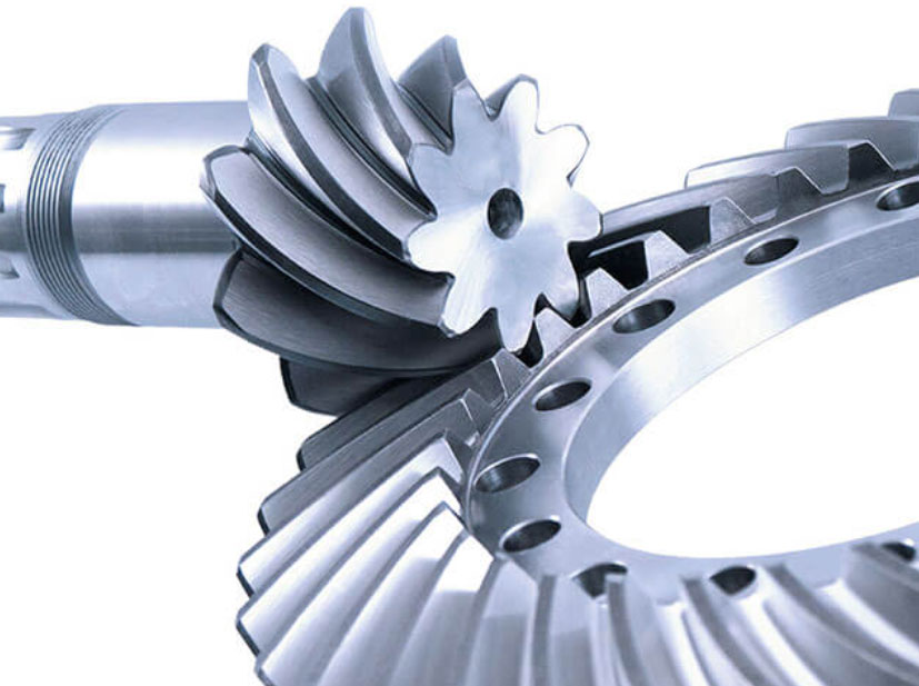
Analyzing stress distribution in spiral bevel gear teeth is crucial to ensure the gears’ structural integrity and performance. Finite Element Method (FEM) simulations are widely used for stress analysis in gear design and optimization. Here’s how FEM simulations can help analyze stress distribution in spiral bevel gear teeth:
1. Gear Model Creation:
- The first step in FEM simulation is to create a 3D model of the spiral bevel gear using specialized CAD software. The model includes detailed geometry of the gear teeth, gear shafts, and other relevant components.
2. Mesh Generation:
- The gear model is then divided into small finite elements to create a mesh. Mesh generation is crucial for accurate stress analysis, as it determines how well the model represents the actual geometry.
3. Material Properties and Boundary Conditions:
- Material properties of the gear material, such as Young’s modulus, Poisson’s ratio, and yield strength, are input into the simulation. Boundary conditions, such as fixed support and rotational forces, are also defined to simulate real-world operating conditions.
4. Loads and Constraints:
- External loads acting on the gear teeth, such as tangential forces due to torque or bending loads, are applied in the simulation. Constraints are also applied to the gear model to represent how the gear interacts with its surrounding components.
5. Solving the Equations:
- The FEM software solves the governing equations of stress and deformation for each finite element in the gear model. The simulation calculates the stresses, strains, and displacements in the gear teeth under the applied loads.
6. Stress Analysis:
- The FEM simulation generates a stress distribution map that shows the stress levels across the gear teeth. This map helps identify high-stress regions, such as the tooth root and fillet areas, which are critical for gear strength and fatigue life.
7. Fatigue Analysis:
- By combining the stress distribution results with material fatigue properties, engineers can assess the gear’s fatigue life and potential failure points. This information is crucial for ensuring the gear’s reliability in long-term operation.
8. Optimization:
- FEM simulations allow for iterative design optimization. Engineers can modify the gear geometry, material, or other parameters to improve stress distribution, reduce high-stress regions, and enhance gear performance.
9. Verification and Validation:
- The FEM results can be compared to analytical calculations or experimental measurements to verify the accuracy of the simulation. Validating the simulation results ensures that the gear design meets the desired safety factors and performance requirements.
FEM simulations provide valuable insights into the stress distribution in spiral bevel gear teeth, helping engineers design gears with optimal strength and performance. By using FEM analysis in gear design, manufacturers can ensure that their spiral bevel gears are structurally sound, reliable, and capable of withstanding the demands of their intended applications.
