Abstract
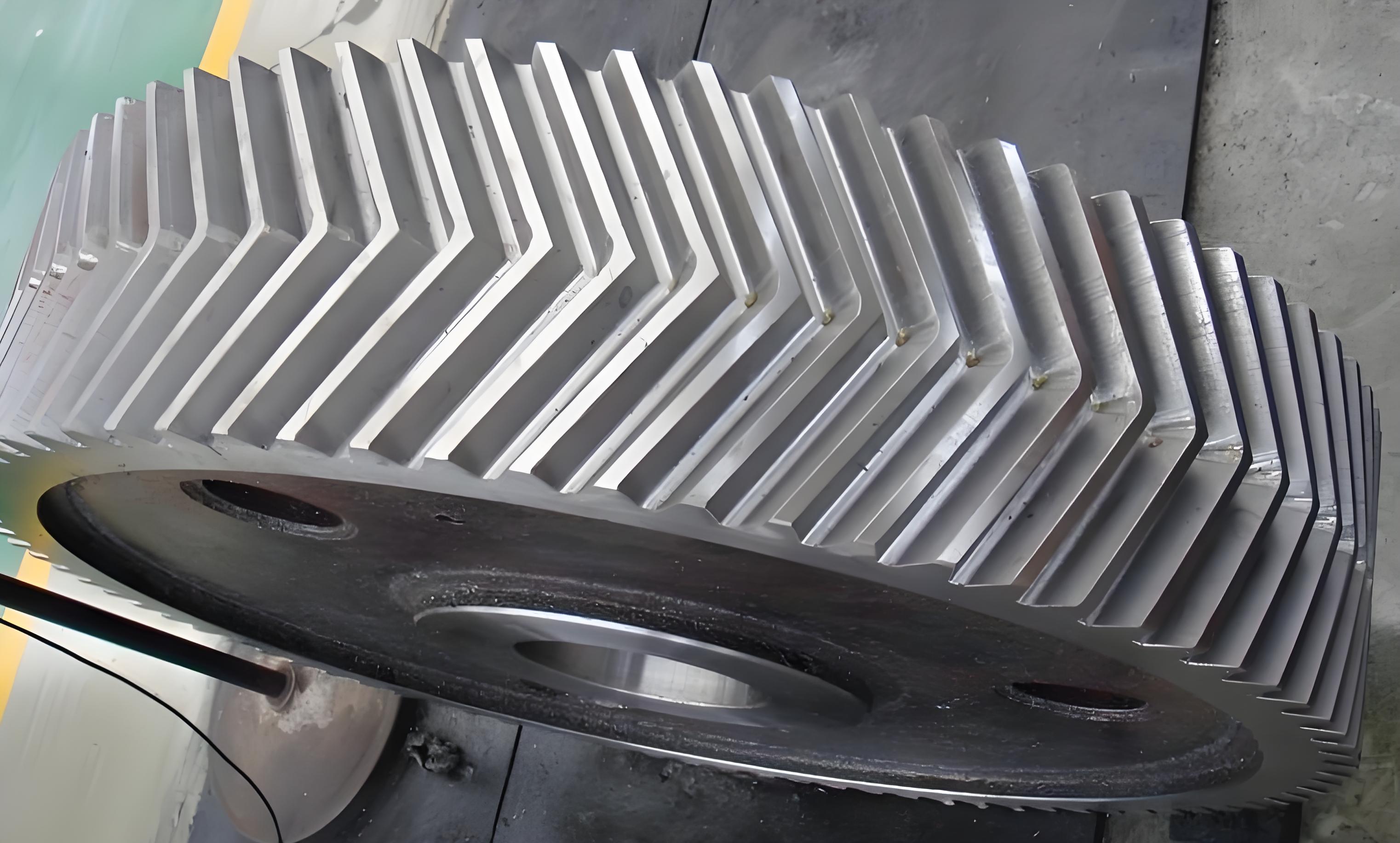
The anti-scuffing load calculation method of herringbone gears, incorporating the theories of Thermal Elastohydrodynamic Lubrication (TEHL) and heat transfer. By considering the effects of centering errors and shaft angle errors, an equivalent meshing model for herringbone gears is developed. The frictional heat flow density, convective heat transfer coefficients, and boundary conditions are analyzed to derive the gear body’s temperature field. An iterative process between the mixed TEHL model and heat conduction model is established to propose an anti-scuffing load calculation method, which is validated through equivalent scuffing tests.

Keywords: herringbone gear; thermal elastohydrodynamic lubrication; anti-scuffing load; centering error; shaft angle error
1. Introduction
Herringbone gears are widely used in high-speed and heavy-load applications due to their excellent load-carrying capacity and stability. However, under severe operating conditions, scuffing failure can occur due to excessive frictional heat and lubrication deterioration. Therefore, it is crucial to investigate the anti-scuffing load calculation method of herringbone gears.
Table 1: Research Status of Key Areas Related to Gear Scuffing
| Research Area | Current Status |
|---|---|
| Gear Contact Temperature | Various models and numerical methods have been developed to predict gear contact temperatures. |
| Gear Errors | Centering errors and shaft angle errors significantly impact gear performance. |
| Elastohydrodynamic Lubrication (EHL) | Mixed EHL models consider rough surface asperities and lubricant properties. |
| Gear Anti-Scuffing Capacity | Existing methods are often simplified and lack accuracy in considering multi-factor coupling effects. |
2. Construction of Herringbone Gear TEHL Contact Model
2.1 Equivalent Meshing Analysis of Herringbone Gears
The equivalent meshing model for herringbone gears facilitates the computation of contact line length, gear surface load distribution, and relative sliding speeds. By incorporating mixed TEHL theory, the contact characteristics of herringbone gear surfaces are analyzed.
Table 2: Parameters of Herringbone Gear Equivalent Meshing Model
| Parameter | Description |
|---|---|
| Contact Line Length | Length of the line where two gear teeth contact. |
| Gear Surface Load Distribution | Distribution of load on the gear tooth surface. |
| Relative Sliding Speed | Speed difference between two contacting surfaces. |
2.2 TEHL Model Construction
The TEHL model for herringbone gears considers the effects of asperity contact and lubricant properties. The mixed TEHL theory is applied to analyze the oil film thickness, pressure distribution, and temperature rise.
3. Anti-Scuffing Load Calculation Method Based on TEHL Contact
3.1 Frictional Heat Flow Density on Herringbone Gear Surfaces
The frictional heat flow density is derived based on the TEHL model and load distribution. It represents the heat generated due to friction between contacting surfaces.
3.2 Heat Conduction Model and Gear Body Temperature Field
The heat conduction model for herringbone gears is established to analyze the convective heat transfer coefficients and boundary conditions of varying gear surfaces. The gear body’s temperature field is obtained by solving the heat conduction equation.
Table 3: Key Parameters of Heat Conduction Model
| Parameter | Description |
|---|---|
| Convective Heat Transfer Coefficient | Heat transfer rate between gear surface and surrounding fluid. |
| Boundary Conditions | Conditions at the boundaries of the heat conduction problem. |
| Gear Body Temperature Field | Distribution of temperature within the gear body. |
3.3 Construction of Anti-Scuffing Load-bearing Model
An iterative process between the mixed TEHL model and heat conduction model is established. The oil film thickness ratio and maximum contact temperature are used as criteria to assess scuffing risk.
3.4 Equivalent Scuffing Test for Herringbone Gears
Equivalent scuffing tests are designed to observe the scuffing evolution on herringbone gear surfaces and validate the proposed anti-scuffing load calculation method.
Table 4: Experimental Setup for Scuffing Test
| Component | Description |
|---|---|
| Test Gearbox | Contains test gears and provides a closed-loop power system. |
| Loading Method | Traditional method using weights hung on the loading lever. |
| Torque Measurement | Read from the torque measurement clutch. |
| Test Procedure | Follows FZG A/8.3/90 test program with specified load levels. |
4. Analysis of Parameters Influencing Anti-Scuffing Load-bearing Capacity
4.1 Results of Anti-Scuffing Load Calculation
The proposed method is used to calculate the anti-scuffing load-bearing capacity of herringbone gears. The results are analyzed to identify key parameters influencing scuffing performance.
4.2 Influence of Gear Parameters on Scuffing Load-bearing Capacity
The effects of centering errors, shaft angle errors, and other gear parameters on scuffing load-bearing capacity are investigated. The results provide insights into optimizing gear design and operation.
Table 5: Influence of Key Parameters on Scuffing Load-bearing Capacity
| Parameter | Influence on Scuffing Load-bearing Capacity |
|---|---|
| Centering Error | Increases scuffing risk by causing load imbalance. |
| Shaft Angle Error | Similar to centering error, affects load distribution and increases scuffing risk. |
| Lubricant Properties | Influence oil film thickness and temperature rise, thereby impacting scuffing resistance. |
5. Conclusions
The anti-scuffing load calculation method for herringbone gears based on TEHL and heat transfer theories. The method considers mixed contact characteristics, centering errors, and shaft angle errors. Equivalent scuffing tests are designed to validate the proposed method. The main conclusions are as follows:
- The proposed anti-scuffing load calculation method provides a theoretical basis for predicting scuffing failure in herringbone gears.
- Centering errors and shaft angle errors significantly impact scuffing load-bearing capacity by affecting load distribution and oil film thickness.
- Equivalent scuffing tests confirm the validity of the proposed method in predicting scuffing failure.
