Flexible wheels are subject to alternating stress with an amplitude twice that of assembly stress. In the structural analysis of flexible wheels, the circumferential bending stress caused by bending moment accounts for the highest proportion of assembly stress, which is the basic index for the design of flexible wheels.
1. Aperture model

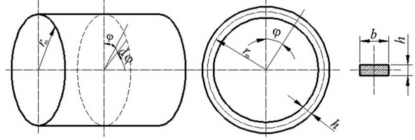
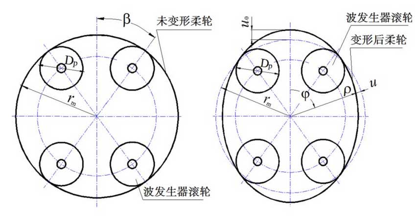
In the cross section perpendicular to the shaft of rotation, the plane ring is intercepted as the calculation model (figure). In figure b, the width of the ring is width of the ring; h, the thickness of the ring; rm, the radius of the circle of the neutral layer of the flexible wheel before deformation; and phi, the polar angle relative to the long axis of the wave generator. In assembly state, the deformation of the flexible wheel is mainly determined by the shape of the wave generator. In this paper, four-roller wave generator is taken as an example, in position beta.Under the action of four Dp diameter rollers (Fig. (a)), the ring is deformed into an ellipse with a pole diameter of rho. The maximum radial deformation at the long axis is U0 (Fig. (b)) and at other locations is u.

2. Aperture force
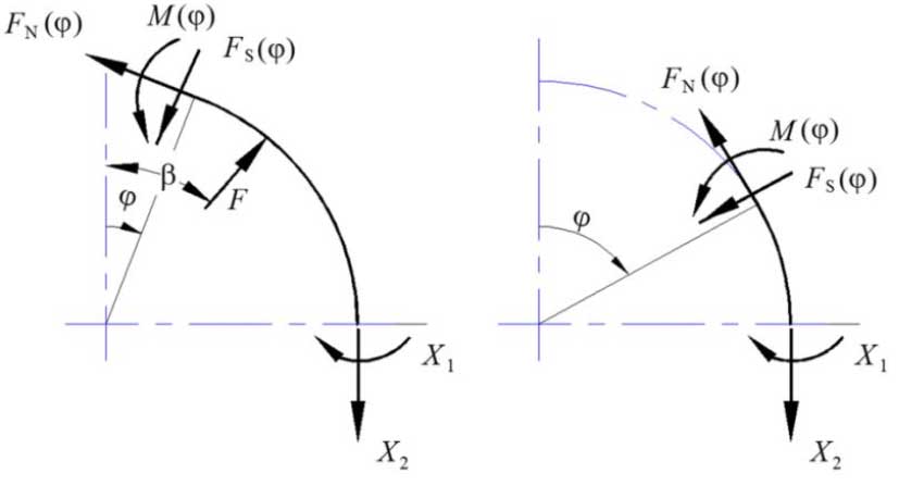
Internal force calculation model for any aperture section is shown in Figure 3. Bending moment M (), circumferential force FN () and shear force FS (_) are generated under the action of roller thrust F. With the help of displacement and angular conditions at the short axis, internal forces X1 and X2 at the short axis can be determined. Bending moment M at any polar angle_can be obtained:
M={Frm(2/pi_cos beta sinphi)(beta <phi < pi/2) Frm(2/pi_sinbeta cosphi)(0 < Phi < beta)) (1)

A) first interval internal force b) second interval internal force
Concentration force of rollers can be obtained from radial displacement of u 0 at_=0
F=2EIZu0rm3 (pi 2cos beta+sinbeta_beta cos beta_4pi) (2)
Formula: section bending moment of inertia Iz=bh3/12; E is material modulus of elasticity.
3. Circumferential bending stress
From_=Mh/2Iz, substituted formula (1) and formula (2), the circumferential bending stress of any section can be obtained.
_={u0Eh (4pi_2sin beta cos_phi) 2rm2 (pi 2cos beta+sinbeta_beta cos beta_4pi) (0 < Phi < beta) u0Eh (4pi_2cos beta sinphi) 2rm2 (pi 2cos beta+sinbeta_beta cos beta_4pi) (beta <phi < PI 2)(3)
The circumferential bending stress varies with the value of_. The maximum circumferential tensile stress is at the roller position beta and the maximum circumferential compressive stress is at the short axle.
