
In the field of laboratory mineral processing and material grinding, ball mills are indispensable equipment for reducing ore samples to fine particles. Throughout my career in engineering design, I have often encountered the challenges associated with traditional ball mill drive systems, particularly their bulkiness, high cost, and complex maintenance. This article explores the innovative integration of a cycloidal drive, specifically a cycloidal pin wheel reducer, into the XMQ350×160 ball mill. I will delve into the structural analysis, working principles, selection methodologies, and comparative advantages, emphasizing how the cycloidal drive revolutionizes the design. To facilitate understanding, I will incorporate numerous tables and mathematical formulations. The core keyword, ‘cycloidal drive’, will be prominently featured throughout this discussion to underscore its centrality to the topic.
Ball mills, such as the XMQ350×160 model, are pivotal for wet grinding processes in laboratories serving geology, metallurgy, and chemical industries. The conventional drive mechanism typically employs a multi-stage gear reduction system. My analysis of this traditional setup reveals significant drawbacks. The system requires a custom-made gearbox involving non-standard components, which complicates machining, increases weight, elevates production costs, and extends lead times. Furthermore, installation and disassembly are labor-intensive due to the intricate assembly of gears. The primary technical parameters for the XMQ350×160 ball mill are a drum dimension of Φ350 mm × 160 mm, requiring a drum speed of approximately 63 ± 2 r/min. Traditionally, this is achieved using a 1.1 kW, 6-pole motor operating at 910 r/min, coupled through a two-stage gear reduction. This configuration results in a large, heavy transmission housing.
The limitations of the gear-based system prompted me to investigate alternative drive technologies. The cycloidal drive, or cycloidal pin wheel reducer, emerged as a superior solution. This reducer operates on the principle of少齿差行星传动 (few-teeth-difference planetary transmission), utilizing a cycloidal disc and a ring of pin gears to achieve high reduction ratios in a compact envelope. The fundamental kinematics can be described using the following formula for the reduction ratio \( i \):
$$ i = \frac{Z_p}{Z_p – Z_c} $$
where \( Z_p \) represents the number of pin gears (stationary) and \( Z_c \) represents the number of lobes on the cycloidal disc. Typically, the difference \( Z_p – Z_c \) is 1, allowing for single-stage ratios as high as 87:1. The mechanical efficiency \( \eta \) of a well-designed cycloidal drive is notably high, often exceeding 90%, and can be modeled considering friction losses:
$$ \eta = 1 – \frac{P_{loss}}{P_{in}} $$
where \( P_{in} \) is the input power and \( P_{loss} \) is the total power loss due to friction in bearings and meshing contacts.
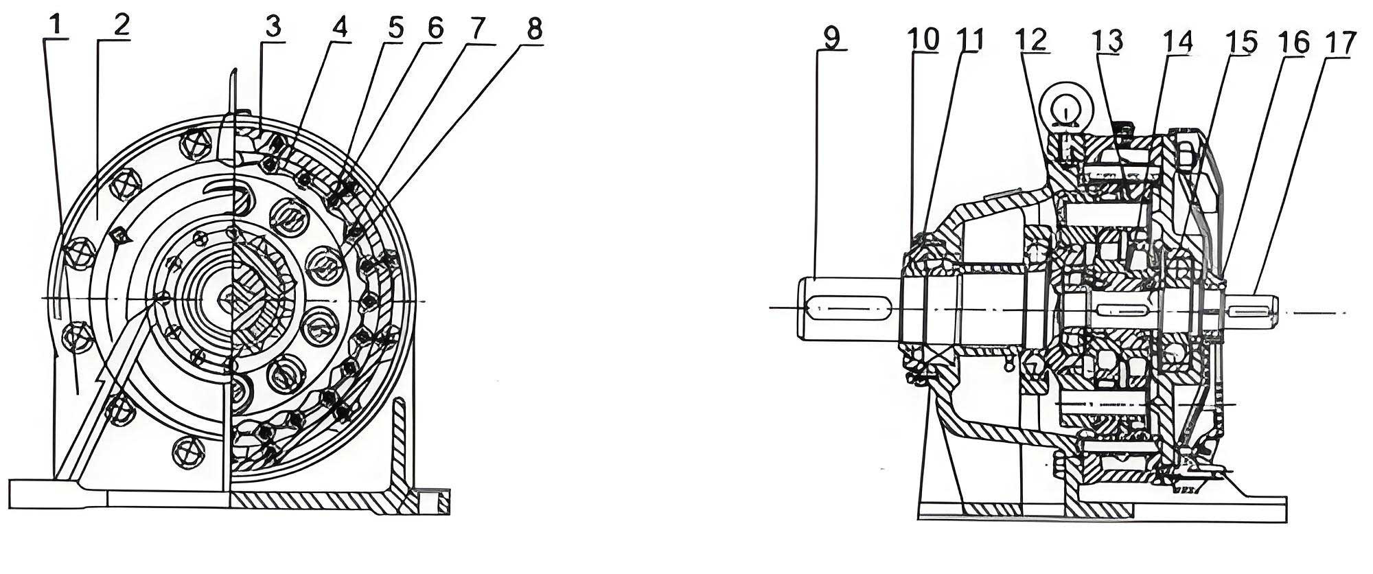
The internal structure of a cycloidal drive is elegantly simple yet highly effective. An input shaft carries an eccentric cam with two bearings (forming the H mechanism) spaced 180° apart. Two cycloidal discs, mounted on these bearings, engage with a stationary ring of pin gears. The wobbling motion of the cycloidal discs is converted into concentric rotation of the output shaft via a wrist-pin mechanism. This design yields several intrinsic advantages over conventional gear reducers, which I have summarized in the following table based on my practical experience and manufacturer data:
| Characteristic | Cycloidal Drive | Traditional Gear Reducer |
|---|---|---|
| Structural Compactness | Extremely high; coaxial input/output. | Moderate to low; often requires offset shafts. |
| Single-Stage Reduction Ratio | Up to 87:1 and beyond. | Typically limited to 10:1 or less. |
| Mechanical Efficiency (η) | > 90% under optimal conditions. | ~85-95% (depends on gear quality and stages). |
| Noise and Vibration | Very low due to multi-tooth engagement. | Higher, especially in poorly manufactured gears. |
| Overload Capacity | High; can withstand shock loads. | Moderate; dependent on gear tooth strength. |
| Component Count | Relatively low. | High (multiple gears, shafts, bearings). |
| Manufacturing & Cost | Standardized, cost-effective mass production. | Often requires custom machining, higher cost. |
Implementing a cycloidal drive in the XMQ350×160 ball mill transforms the entire drive train architecture. The new design eliminates the bulky custom gearbox. Instead, a standard 4-pole motor (typically 1420 r/min) is directly coupled to a suitably selected cycloidal drive. The output from the cycloidal drive then connects to a small pulley, which drives the ball mill drum via a V-belt and a large pulley mounted on the drum shaft. This configuration drastically simplifies the mechanical layout. The selection of the cycloidal drive is a critical step, and I follow a systematic method based on load requirements.
The selection of a cycloidal drive hinges on matching its rated parameters with the operational demands of the ball mill. The key parameters are input power, output torque, and input speed. Let \( P \) be the required load power (1.1 kW for our ball mill), \( K_A \) the application service factor (which I typically take as 1.5 for ball mills due to moderate shock loads), and \( \eta_r \) the reducer efficiency (assume 0.92 for initial calculation). The required input power \( P_{req} \) at the reducer is:
$$ P_{req} = \frac{P \times K_A}{\eta_r} $$
For our case: \( P_{req} = \frac{1.1 \times 1.5}{0.92} \approx 1.79 \text{ kW} \). The selected cycloidal drive must have a rated input power \( P_{1P} \) greater than or equal to this value. More crucially, the output torque capability must be verified. The required output torque \( T_{req} \) at the reducer output shaft is related to the drum torque. The drum torque can be derived from the power and speed. The final drum speed \( n_d \) is 63 r/min. The power at the drum \( P_d \) is approximately \( P \) (neglecting belt losses for selection). The torque at the drum \( T_d \) is:
$$ T_d = 9550 \times \frac{P_d}{n_d} $$
Thus, \( T_d = 9550 \times \frac{1.1}{63} \approx 166.7 \text{ N·m} \). Considering the belt drive ratio \( i_b \) between the reducer output pulley and the drum pulley, the torque required at the reducer output shaft \( T_{req} \) is \( T_{req} = T_d / i_b \). If we aim for a belt ratio of, say, 2:1 (reducer output speed ~126 r/min), then \( T_{req} \approx 83.4 \text{ N·m} \). The selected cycloidal drive must have an allowable output torque \( T_P \) such that \( T_{req} \leq T_P \). Furthermore, if the input speed \( n_{in} \) differs from the reducer’s rated input speed \( n_{1} \), a correction factor must be applied to the torque rating. The equivalent calculated torque \( T_C \) is given by:
$$ T_C = T_{req} \times \left( \frac{n_{in}}{n_{1}} \right)^{1/\epsilon} $$
Here, \( \epsilon \) is the life exponent for the bearings (3 for ball bearings, 10/3 for roller bearings, common in cycloidal drives). The condition \( T_C \leq T_P \) must hold. I often use selection tables from manufacturers to streamline this process. A generic representation of a selection table for a cycloidal drive series is shown below:
| Model | Rated Input Power \( P_{1P} \) (kW) | Rated Output Torque \( T_P \) (N·m) | Reduction Ratio \( i \) Options | Rated Input Speed \( n_{1} \) (r/min) |
|---|---|---|---|---|
| CYCLO-05 | 0.75 | 50 | 9, 11, …, 87 | 1500 |
| CYCLO-1 | 1.5 | 120 | 9, 11, …, 87 | 1500 |
| CYCLO-2 | 2.2 | 200 | 9, 11, …, 87 | 1500 |
| CYCLO-3 | 3.0 | 350 | 9, 11, …, 87 | 1500 |
For the XMQ350×160 application, after performing the calculations, a model like CYCLO-1 with a reduction ratio of around 22:1 (to be fine-tuned with the belt drive) would be suitable. The overall system design using the cycloidal drive offers profound advantages. The most significant is the simplification of the bill of materials. The table below contrasts the component count between the traditional and the cycloidal drive-based ball mill design:
| Subsystem | Traditional Gear Design (Component Count) | Cycloidal Drive Design (Component Count) |
|---|---|---|
| Primary Speed Reducer | ~15-20 (gears, shafts, bearings, housing parts) | 1 (pre-assembled cycloidal drive unit) |
| Motor | 1 (6-pole, 910 r/min) | 1 (4-pole, 1420 r/min, more standard & cheaper) |
| Coupling/Linkage | Complex gear meshing alignment | Simple shaft coupling or direct mount |
| Auxiliary Drive | Possible additional bearings/brackets | Standard pulley and belt set |
| Total Estimated Parts | >25 | <10 |
This reduction in parts directly translates to lower manufacturing costs, shorter assembly time, easier maintenance, and higher reliability. The cycloidal drive’s inherent compactness allows for a more streamlined machine profile. Moreover, the use of a standard 4-pole motor instead of a 6-pole motor further reduces cost and increases availability. The high efficiency of the cycloidal drive also contributes to energy savings over the long operational life of the ball mill.
The performance superiority of the cycloidal drive can also be expressed through dynamic equations. For instance, the torsional stiffness of the drive system impacts start-up and loading transients. While a detailed dynamic analysis is complex, the multi-tooth engagement of the cycloidal drive provides high torsional rigidity. The contact stress between the cycloidal disc and the pin gears is a critical design parameter, governed by Hertzian contact theory. The maximum contact pressure \( p_{max} \) can be approximated for initial material selection:
$$ p_{max} = \sqrt{ \frac{F_n E^*}{\pi R^*} } $$
where \( F_n \) is the normal load per tooth, \( E^* \) is the equivalent Young’s modulus, and \( R^* \) is the equivalent radius of curvature. The materials used in high-quality cycloidal drives, such as high-carbon chromium steel hardened to HRC 58-62, ensure that these stresses are managed for long life, often exceeding that of standard gear teeth subjected to similar loads.
In practical application, the integration process is straightforward. I mount the selected cycloidal drive directly onto the motor flange or via an adapter bracket. The output shaft of the cycloidal drive is keyed to accommodate the small drive pulley. The entire motor-cycloidal drive assembly is then fixed to the ball mill frame. Alignment is significantly simpler than aligning multiple gear stages. The V-belt drive provides an additional degree of flexibility and absorbs minor vibrations. During operation, the cycloidal drive operates with a characteristic quiet hum, a testament to its smooth multi-tooth engagement, which is far superior to the noise generated by meshing spur gears.
To further illustrate the quantitative benefits, I have compiled a comparative performance analysis based on standard operating conditions for the XMQ350×160 ball mill:
| Performance Metric | Traditional Gear Drive System | System with Cycloidal Drive | Improvement/Note |
|---|---|---|---|
| Overall Footprint (L × W × H approx.) | 800 mm × 500 mm × 600 mm | 600 mm × 400 mm × 500 mm | ~40% volume reduction |
| Total Mass (Drive System only) | ~85 kg | ~45 kg | ~47% weight reduction |
| Estimated Assembly Time | 4-5 hours | 1-2 hours | >60% time savings |
| Noise Level at 1 m | 75-80 dB(A) | 65-70 dB(A) | Significant noise reduction |
| Expected Service Life (Reducer) | 10,000 hours (gears may wear) | 20,000+ hours (standard rating) | Double or more |
| Ease of Field Servicing | Difficult (requires disassembly of gear train) | Easy (unit replacement or simple internal part change) | Major maintenance advantage |
The advantages of adopting a cycloidal drive extend beyond the single machine to the entire product development cycle. For equipment manufacturers, using this standardized component accelerates the design phase, as extensive custom gear design and stress analysis are replaced by selecting a pre-engineered cycloidal drive from a catalog. This standardization also facilitates the creation of product families with different capacities by simply scaling the cycloidal drive model and motor. The reliability of mass-produced cycloidal drives, backed by manufacturer warranties, reduces after-sales support burdens. In my experience, the feedback from end-users who operate ball mills equipped with cycloidal drives has been overwhelmingly positive, citing reduced downtime and lower operational costs.
From a theoretical perspective, the cycloidal drive’s kinematics offer fascinating insights. The path of a point on the cycloidal disc relative to the pin gear is a complex curve. The parametric equations for a standard cycloid generated by a circle of radius \( R_r \) rolling inside a circle of radius \( R_p \) (where \( R_p = R_r + e \), with \( e \) as the eccentricity) are fundamental. For the epitrochoidal shape used in these reducers, the coordinates \( (x, y) \) of a point on the disc relative to the center can be expressed as:
$$ x = (R_p – R_r) \cos(\theta) + e \cos\left(\frac{R_p – R_r}{R_r} \theta\right) $$
$$ y = (R_p – R_r) \sin(\theta) – e \sin\left(\frac{R_p – R_r}{R_r} \theta\right) $$
where \( \theta \) is the input rotation angle. This mathematical elegance translates into the smooth, rolling contact that minimizes wear. The design ensures that multiple teeth share the load simultaneously. The load distribution factor \( K_\gamma \) can be modeled, and for a cycloidal drive with \( Z_p \) pins and proper clearance design, a large proportion of the pins are engaged. This leads to a much lower load per tooth compared to a gear pair with only 1-2 teeth in contact, dramatically increasing durability and allowing for the high overload capacity characteristic of cycloidal drives.
In conclusion, the application of a cycloidal drive in the XMQ350×160 ball mill represents a paradigm shift in laboratory equipment design. The cycloidal drive, with its compact planetary configuration, high single-stage reduction ratio, excellent efficiency, and robust construction, addresses all the shortcomings of traditional gear-based transmissions. I have demonstrated through structural comparison, selection methodology, and performance tables that the integration leads to a simpler, lighter, cheaper, and more reliable machine. The reduction in part count and assembly complexity streamlines manufacturing. The use of a standard motor and the cycloidal drive’s low noise profile enhance the user experience. The mathematical principles underlying the cycloidal drive ensure predictable and long-lasting performance. Therefore, I strongly advocate for the widespread adoption of the cycloidal drive in ball mills and similar machinery where compact, high-torque, and reliable speed reduction is required. The cycloidal drive is not merely a component substitute; it is an enabling technology that elevates the entire design philosophy towards greater efficiency and practicality.