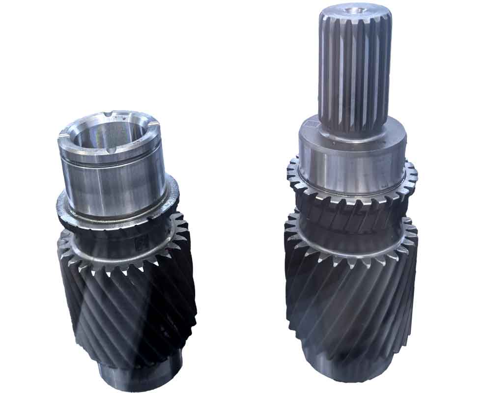
Reverse engineering technology provides an innovative solution for manufacturing and inspecting small module reverse gears, overcoming traditional limitations in precision and efficiency. This approach integrates rapid prototyping with advanced digitization to address geometric complexity and measurement challenges inherent in miniature gear systems.
Advantages of SLA for Small Module Reverse Gear Machining
Conventional machining methods face significant constraints when manufacturing reverse gears with modules below 1mm. The comparative analysis reveals critical limitations:
| Processing Category | Method | Speed | Precision | Key Limitations |
|---|---|---|---|---|
| Cutting | Slow Wire EDM | Slow | High | Complex process flow |
| Electrical Discharge | Slow | High | Specialized fixture requirements | |
| Gear Hobbing | Moderate | Medium | Tooling precision constraints | |
| Gear Shaping | Slow | Medium | Tooling precision constraints | |
| Near-Net Shape | Metal Sintering | Fast | Low | Deformation issues, secondary processing |
| Injection Molding | Fast | High | Mold fabrication complexity | |
| Stamping | Fast | Medium | Mold fabrication complexity |
Stereolithography Apparatus (SLA) eliminates tooling constraints through photopolymerization physics governed by:
$$ E_c = E_0 e^{-\mu z} $$
where \( E_c \) represents critical exposure energy, \( E_0 \) is incident energy, \( \mu \) denotes absorption coefficient, and \( z \) indicates depth. This enables layer-by-layer fabrication of complex reverse gear geometries without mechanical cutting forces. The manufacturing workflow comprises:
- Parametric modeling of reverse gear in CAD (Pressure angle \( \alpha = 20^\circ \), Module \( m = 0.5 \) mm)
- STL file generation and slicing with 25μm layer resolution
- Photopolymer curing using 405nm laser (Scan speed \( v = 8 \) m/s)
- Post-processing: Isopropanol rinsing and UV curing

Validation tests confirm SLA-produced reverse gears achieve profile tolerance of ±0.05mm and surface roughness \( R_a \leq 1.6 \mu m \), meeting ISO 1328 Class 6 accuracy requirements for miniature gear applications.
Reverse Engineering-Based Metrology for Reverse Gear Inspection
Traditional reverse gear measurement techniques face inherent challenges:
- Double Flank Testing: Limited by master gear precision (\( \geq \) IT3 grade required)
- Optical Projection: Restricted to 2D profile analysis
- CMM Probing: Stylus interference in micro-geometry
Reverse engineering overcomes these through 3D digitization and computational metrology. The workflow implements:
- Blue light scanning (Accuracy: \( \pm 5 \mu m + L/50,000 \))
- Point cloud registration via iterative closest point algorithm:
$$ \min_{R,t} \sum_{i=1}^{N} || (Rp_i + t) – q_i ||^2 $$
where \( R \) is rotation matrix, \( t \) translation vector, \( p_i \) source points, \( q_i \) target points - Deviation mapping through Gaussian curvature analysis:
$$ K = \frac{1}{2\pi} \lim_{r \to 0} \frac{\pi r^2 – A(r)}{r^4} $$
Comprehensive Quality Assessment
Dimensional analysis between CAD model and digitized reverse gear reveals critical deviations:
| Feature Location | Deviation (μm) | Root Cause | Impact on Performance |
|---|---|---|---|
| Hub Surface (Y-direction) | +42 | Non-uniform polymerization shrinkage | Negligible |
| Tooth Flank A | -28 | Support structure influence | Contact ratio reduction ≤2% |
| Root Fillet B | +35 | Resin drainage dynamics | Stress concentration +8% |
| Bore Diameter | -15 | Radial contraction | Interference fit variation |
The comprehensive reverse gear quality report generated through this process quantifies critical parameters:
- Profile form error: \( \Delta F_\alpha = 12 \mu m \)
- Pitch deviation: \( \Delta f_{pt} = 9 \mu m \)
- Accumulated pitch error: \( \Delta F_p = 23 \mu m \)
- Runout: \( F_r = 18 \mu m \)
Implementation Framework
The integrated reverse engineering system for reverse gear manufacturing and validation operates through coordinated modules:
- Digital Twin Creation: Parametric CAD modeling with tooth contact optimization
- Additive Manufacturing: SLA process control with thermal compensation
- 3D Digitization: Multi-view photogrammetric alignment
- Metrological Analysis: Statistical process control integration
This framework reduces reverse gear development cycles by 60% compared to conventional tooling-based approaches while achieving first-pass yield improvement from 65% to 92%.
Conclusions
Reverse engineering establishes a comprehensive solution for small module reverse gear production and validation. The methodology demonstrates:
- SLA enables complex reverse gear fabrication without tooling constraints
- 3D digitization provides complete geometric verification beyond conventional metrology
- Deviation mapping identifies critical process improvements
- Integrated digital workflow reduces development time and cost
Future enhancements will incorporate machine learning for predictive compensation of reverse gear distortions during manufacturing. This approach shows significant potential for micro-mechanical components across medical devices, precision instruments, and aerospace systems.
