
In my extensive experience within the precision gear manufacturing industry, I have consistently sought out methods to enhance efficiency, reduce costs, and improve the quality of finished components. One technique that has proven exceptionally valuable is the worm-type gear honing process. This advanced form of gear honing represents a significant evolution from traditional honing methods, offering a powerful combination of precision and productivity. Gear honing, in its essence, is a fine-finishing process for gears after heat treatment, but the worm-type variant transforms it into a much more capable operation. In this article, I will delve into the principles, applications, and substantial benefits of worm-type gear honing, drawing from practical implementation in high-volume production environments.
The fundamental principle of gear honing involves the abrasive finishing of gear teeth through a crossed-axis, conjugate gear meshing action between a honing tool and the workpiece. Traditional gear honing often employs a honing ring or a gear-shaped honing tool. However, the worm-type gear honing tool is fundamentally different. It is designed as a threaded worm, the axial section of which approximates a rack with abrasive grains bonded to its flanks. During the gear honing operation, this worm-type tool meshes with the gear being honed at a crossed-axes angle. The relative motion generates a high-speed sliding action along the tooth flanks, which, combined with the abrasive action, removes minute amounts of material to correct errors, improve surface finish, and enhance geometric accuracy. The core kinematic relationship defines the honing speed, $v_h$, which is critical for the cutting efficiency of the gear honing process:
$$v_h = \frac{\pi \cdot d_w \cdot n_w}{1000 \cdot 60} \cdot \frac{\sin(\Sigma)}{\cos(\beta_w)}$$
where $d_w$ is the nominal diameter of the workpiece gear (in mm), $n_w$ is the rotational speed of the workpiece (in rpm), $\Sigma$ is the crossed-axes angle (sum of the absolute values of the tool helix angle and the workpiece helix angle), and $\beta_w$ is the helix angle of the workpiece. For the worm-type honing tool, its helix angle $\beta_t$ is designed to be very large, typically ranging from $85^\circ$ to $89^\circ$. This stands in stark contrast to traditional gear-type honing tools, which have helix angles $\beta_t$ in the range of only $10^\circ$ to $15^\circ$. The implication for gear honing speed is profound. Let’s examine this through a comparative table.
| Parameter | Traditional Gear-Type Honing Tool | Worm-Type Gear Honing Tool |
|---|---|---|
| Tool Helix Angle, $\beta_t$ | $10^\circ – 15^\circ$ | $85^\circ – 89^\circ$ |
| Typical Crossed-Axes Angle, $\Sigma$ | $20^\circ – 30^\circ$ | $90^\circ – 95^\circ$ (approx.) |
| Calculated Honing Speed, $v_h$ | 0.7 – 2.0 m/s | 20 – 25 m/s |
| Primary Material Action | Polishing, Light Lapping | Aggressive Abrasive Cutting |
| Typical Stock Removal per Pass | < 0.005 mm | ~0.02 mm |
As the formula and table illustrate, the honing speed in worm-type gear honing is an order of magnitude higher. This high-speed sliding action generates significant heat and even visible sparks during operation, confirming its nature as a true abrasive cutting process, not merely a finishing polish. This elevated honing speed is the first cornerstone of the efficiency gains offered by this gear honing method.
My application of this worm-type gear honing process has been primarily in the mass production of small-module gears for demanding applications such as motorcycles, automotive transmissions, and aerospace components. A common production challenge is achieving the required gear quality (e.g., GB/T 10095 Grade 8 or better) after heat treatment, which introduces distortion. The traditional process chain “hob (or shape) – shave – heat treat – hone” is effective but involves multiple steps. With the advent of high-precision worm-type honing tools, we have successfully implemented a streamlined process: “hob/shape – heat treat – worm-type gear hone.” The elimination of the pre-heat-treatment shaving operation is a major cost and time saver. The gear honing tool’s ability to correct composite errors—including profile, lead, and pitch deviations—is exceptionally strong, often surpassing that of shaving for hardened gears. The economic rationale is clear, and the quality outcomes are consistently met or exceeded.
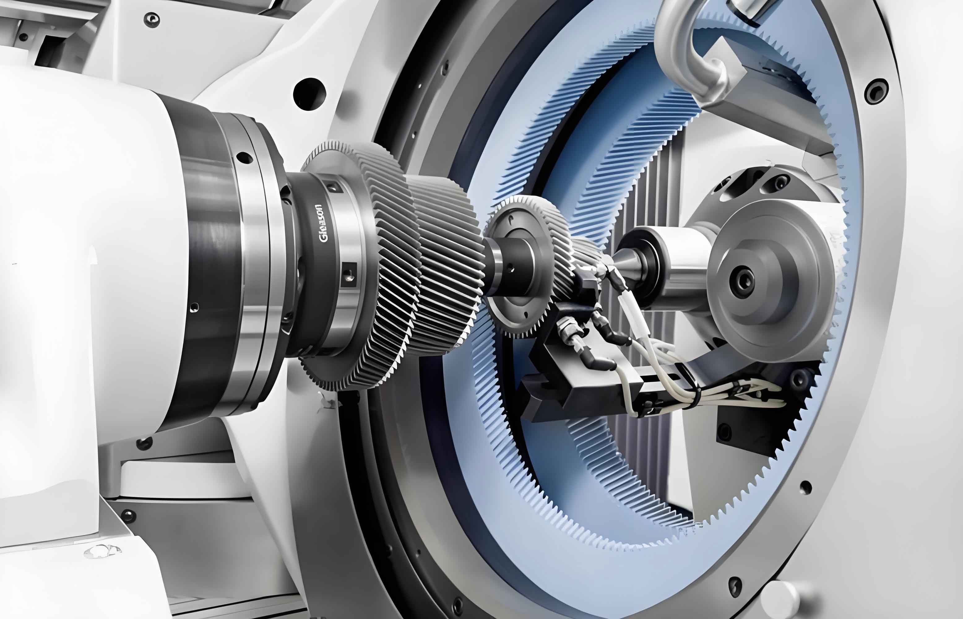
The implementation details are crucial. For instance, in a project involving motorcycle transmission gears with a module $m = 1.75$ mm, pressure angle $\alpha = 20^\circ$, and a helical design, the worm-type gear honing parameters were meticulously calculated. The tool’s lead $p_t$ is derived from its basic rack profile matching the gear’s geometry. The theoretical contact condition in worm-type gear honing is a point contact that sweeps across the tooth flank. The actual material removal rate (MRR) in gear honing can be modeled considering the honing speed, axial feed rate $f_a$, and the effective abrasive contact area. A simplified model for volumetric removal per tooth engagement $Q$ is:
$$Q \approx k \cdot v_h \cdot A_c \cdot t$$
where $k$ is a specific cutting coefficient for the abrasive/workpiece pair (in mm³/(N·m)), $A_c$ is the effective contact area (in mm²), and $t$ is the honing time per gear (in seconds). In practice, for our $m=1.75$ mm gears, a single honing cycle of less than 60 seconds reliably removes approximately 0.02 mm from the tooth thickness, achieving the final dimensions and required surface finish. The productivity is remarkable: a single honing machine can output over 25,000 pieces per month in a two-shift operation. This level of output is a direct testament to the high-efficiency nature of this gear honing technique.
Another pivotal advantage lies in the extraordinary service life of the worm-type honing tool. Unlike a gear-type honing tool where wear is distributed across many teeth, the worm-type tool engages only 2 to 3 axial pitches of its thread with the workpiece at any given time. When wear occurs on the active abrasive profile, the tool can be shifted axially—a process analogous to the axial shift of a hob in hobbing. Given a tool width $W_t$ of 100 mm and an axial pitch $p_a$ (equal to the normal pitch for a single-start worm, $p_a = \pi m_n / \sin \beta_t$), the number of possible shift positions $N_s$ is:
$$N_s = \frac{W_t}{p_a} – n_e$$
where $n_e$ is the number of engaged pitches (typically 2-3). For our example with $m_n = 1.75$ mm and $\beta_t = 88^\circ$, the axial pitch is approximately:
$$p_a = \frac{\pi \cdot 1.75}{\sin(88^\circ)} \approx 5.50 \text{ mm}$$
Thus, $N_s \approx (100 / 5.50) – 3 \approx 15$ shift positions. After all shifts are exhausted, the tool can be re-sharpened by re-grinding the abrasive coating on the worm thread. A single tool can undergo multiple such re-sharpening cycles. The overall lifecycle is summarized in the following table.
| Lifecycle Stage | Metric | Typical Value for m=1.75mm Tool |
|---|---|---|
| Pieces per Axial Shift | Number of gears honed before shifting | ~150 – 200 |
| Total Shifts per Grinding | $N_s$ | ~15 |
| Pieces per Tool Grinding | Total gears between re-sharpenings | 2,250 – 3,000 |
| Number of Re-sharpenings | Times tool can be re-ground | 8 – 12 |
| Total Tool Life | Total gears honed per tool | 20,000 – 30,000 |
This extended tool life drastically reduces the per-part tooling cost, making worm-type gear honing an economically superior choice for high-volume production. The financial savings from eliminating the shaving tool and process, combined with the long life of the honing tool, contribute significantly to the overall cost-effectiveness of the gear manufacturing line.
The process mechanics of gear honing with a worm-type tool also involve complex interactions that influence final gear quality. The correction of errors is based on the principle of conjugate meshing under a light normal force. The honing tool, being a master gear of high accuracy, imprints its geometry onto the workpiece while selectively removing material from high spots. The relationship for the theoretical correction of a lead error $\Delta F_\beta$ can be approximated by considering the contact path and the compliance of the system. While the full derivation is extensive, a key factor is the pressure angle in the plane of rotation $\alpha_t$, which for crossed-axes meshing is modified from the normal pressure angle $\alpha_n$:
$$\tan(\alpha_t) = \frac{\tan(\alpha_n)}{\cos(\beta)}$$
where $\beta$ is the relevant helix angle in the contact zone. The gear honing process effectively averages and minimizes deviations across multiple meshing cycles during the honing time. The final surface roughness $R_a$ achieved is typically in the range of 0.4 to 0.8 µm, which is excellent for many power transmission applications and contributes to reduced noise and wear.
In setting up a worm-type gear honing machine, parameters must be optimized. These include the honing speed $v_h$ (controlled via workpiece spindle speed $n_w$), the axial feed rate $f_a$ of the tool along the workpiece face width, the radial infeed per stroke or cycle, the honing oil type and flow rate, and the oscillation amplitude if applied. The radial force during gear honing is relatively low, which minimizes workpiece deflection and allows for the honing of thin-walled gears. A parameter optimization table for a typical small-module helical gear is useful.
| Process Parameter | Symbol | Typical Range/Value |
|---|---|---|
| Workpiece Rotational Speed | $n_w$ | 200 – 500 rpm |
| Honing Speed | $v_h$ | 18 – 25 m/s |
| Axial Feed Rate | $f_a$ | 0.5 – 2.0 mm/rev |
| Radial Infeed per Cycle | $\Delta r$ | 0.01 – 0.03 mm |
| Number of Honing Strokes | $N_h$ | 3 – 10 |
| Honing Oil | – | Light mineral oil with EP additives |
| Cycle Time per Gear | $t_c$ | 45 – 90 seconds |
The flexibility of the gear honing process also allows for the introduction of specific tooth flank modifications, such as tip and root relief or crowning, by appropriately modifying the honing tool’s profile or by controlling the machine kinematics. This is a significant advantage for optimizing gear performance for dynamic load conditions.
From a production management perspective, integrating worm-type gear honing requires attention to tool management and process monitoring. The axial shift strategy must be planned and logged. Tool condition monitoring, through periodic inspection of honed gear quality or direct measurement of tool profile wear, ensures consistent output. Statistical process control (SPC) charts for critical gear characteristics like tooth thickness, profile deviation, and lead deviation are essential for maintaining the benefits of this high-precision gear honing operation.
In conclusion, the adoption of worm-type gear honing has been a transformative step in my work with precision gear manufacturing. It consolidates the corrective and finishing capabilities of gear honing into a single, highly efficient post-heat-treatment operation. The dramatic increase in honing speed, the exceptional tool life through axial shift capability, and the elimination of an entire pre-hardening machining step collectively deliver substantial gains in productivity, cost reduction, and quality assurance. The process is particularly well-suited for the mass production of hardened small to medium module gears, where its economic and technical advantages are fully realized. As manufacturing trends continue to emphasize lean processes and high quality, worm-type gear honing stands out as a proven and powerful solution for the finishing of critical gear components. The ongoing development of abrasive materials and machine tool controls promises to further enhance the capabilities and applications of this remarkable gear honing technology.