
Abstract
The modeling and optimization design of assembly errors in the spindle cutter disc component of a gear milling machine. By utilizing the small displacement torsor theory, we establish error models for geometric elements and investigate the error transmission properties under both series and parallel mating conditions. Furthermore, a tolerance optimization model is proposed, targeting the minimization of tolerance cost while ensuring assembly precision reliability and adhering to tolerance principles. The application value of the proposed method is verified through a case study on the spindle cutter disc component of a gear milling machine.
1. Introduction
Gear milling machines are crucial equipment in the manufacturing industry, and the spindle cutter disc component is a vital part of these machines. The assembly accuracy of this component directly affects the machining accuracy and performance of the gear milling machine. Therefore, it is essential to study the assembly error modeling and optimization design of the spindle cutter disc component to improve its assembly accuracy and reduce manufacturing costs.
2. Literature Review
Previous studies on tolerance modeling and optimization have mainly focused on geometric elements such as cylindrical surfaces and planes. However, there is a lack of research on tolerance modeling for conical surfaces and assembly errors between planes and cones. Additionally, most studies on tolerance optimization have not considered reliability. Therefore, this paper aims to address these gaps by conducting a comprehensive analysis of assembly error modeling and tolerance optimization for the spindle cutter disc component of a gear milling machine.
3. Error Modeling of Geometric Elements
Based on the small displacement torsor theory, we establish error models for geometric elements such as conical surfaces, cylindrical surfaces, and planes. The error formation mechanism of conical surfaces is similar to that of cylindrical surfaces, which can be described as the positional and orientational variations of the actual axis of the cone relative to the ideal axis.
Table 1. Error Models for Geometric Elements
| Geometric Element | Error Model |
|---|---|
| Conical Surface | (α,β,0,u,v,0) |
| Cylindrical Surface | (θ,0,0,u,v,w) |
| Plane | (0,0,0,u,v,θ) |
4. Error Transmission Modeling
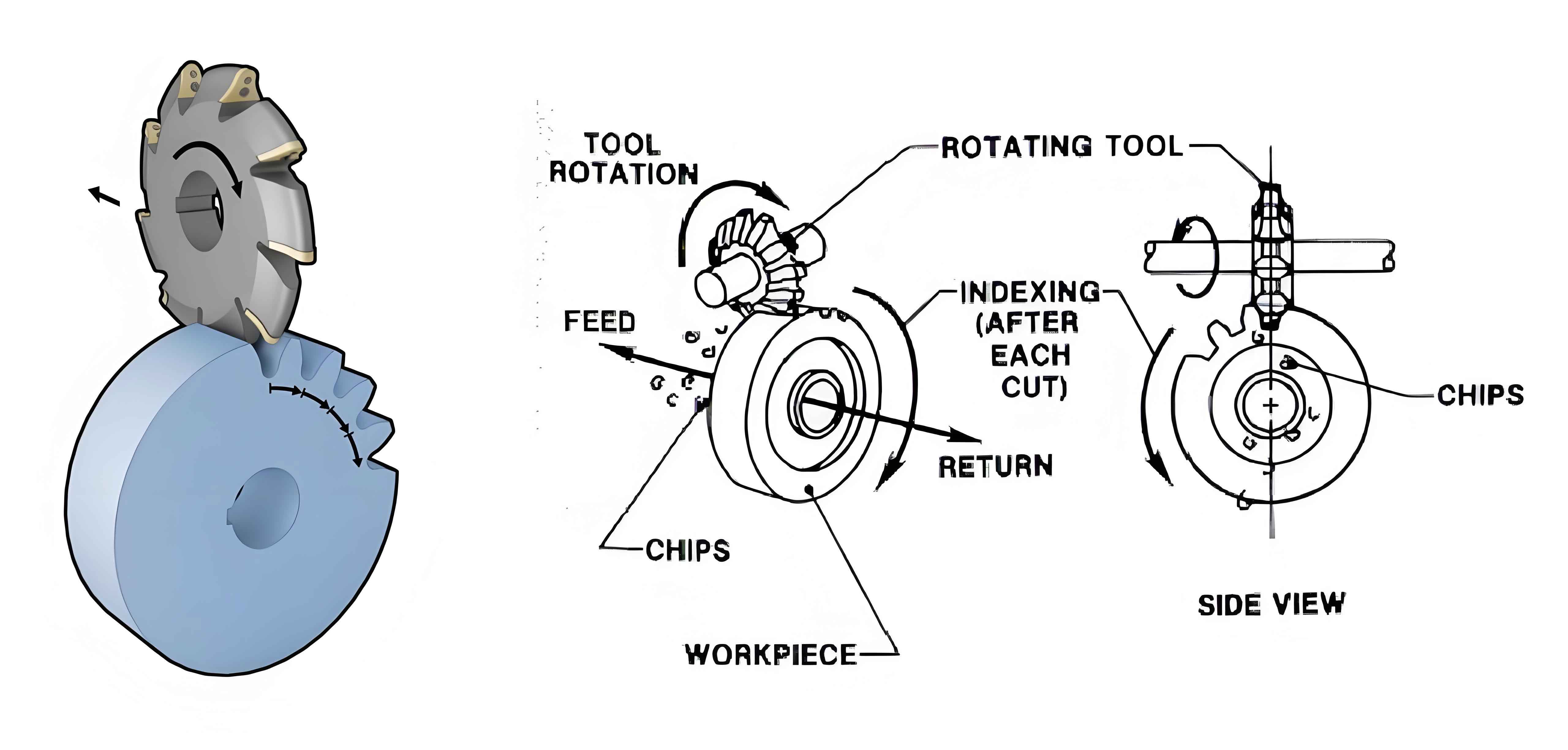
The spindle cutter disc component of a gear milling machine consists of a tool, spindle, and housing. The mating surfaces include conical mating surfaces, cylindrical mating surfaces, and planar mating surfaces. The assembly errors are transmitted from the housing to the spindle and finally to the cutter disc.
Table 2. Mating Surfaces and Tolerance Values
| Mating Surface | Geometric Element | Tolerance Range |
|---|---|---|
| Cylindrical Mating Surface D1 | Inner Cylindrical Surface a | T1=[0.01,0.03] |
| Outer Cylindrical Surface b | T6=[0.01,0.03] | |
| Conical Mating Surface D2 & Planar Mating Surface D3 | Spindle Outer Conical Surface c | T7=[0.002,0.02] |
| Cutter Disc Inner Conical Surface d | T8=[0.002,0.02] | |
| Planar Mating Surface D3 | Cutter Disc Plane e | T9=[0.005,0.02] |
4.1. Error Transmission Calculation for Parallel Mating Surfaces
The error transmission properties of parallel mating surfaces, including conical and planar surfaces, are analyzed. The error transmission attributes are determined based on the mating sequence and the positioning relationship between the mating surfaces.
4.2. Error Transmission Model of the Spindle Cutter Disc Component
The error transmission model of the spindle cutter disc component is established by considering the error variations of each mating surface and the coordinate transformation matrices between them. The assembly error is calculated using the Monte Carlo simulation method.
5. Tolerance Optimization Model
A tolerance optimization model is proposed to minimize the manufacturing cost while ensuring assembly precision reliability and adhering to tolerance principles. The optimization variables include size tolerances, form tolerances, and positional tolerances.
Table 3. Original and Optimized Tolerance Values
| Tolerance Item | Original Tolerance | Optimized Tolerance |
|---|---|---|
| T1 | 0.02 | 0.024 |
| T2 | 0.003 | 0.006 |
| T3 | 0.005 | 0.008 |
| T4 | 0.003 | 0.007 |
| T5 | 0.003 | 0.005 |
| T6 | 0.015 | 0.013 |
| T7 | 0.004 | 0.006 |
| T8 | 0.004 | 0.006 |
| T9 | 0.010 | 0.015 |
| T10 | 0.003 | 0.005 |
6. Results and Discussion
The assembly errors in the x, y, and z directions are simulated using the Monte Carlo method. The maximum assembly errors are found to be 0.052 mm, 0.043 mm, and 0.009 mm, respectively.
Experimental validation is conducted using a laser scanner to obtain point cloud data of the spindle cutter disc component. The assembly errors obtained from the experiment are compared with the simulation results, and the agreement between them verifies the correctness of the assembly error transmission model.
Table 4. Comparison of Experimental and Simulation Results
| Direction | Experimental Error (mm) | Simulation Error (mm) |
|---|---|---|
| x | 0.018 | 0.052 |
| y | 0.006 | 0.043 |
7. Conclusion
The comprehensive study on the modeling and optimization design of assembly errors in the spindle cutter disc component of a gear milling machine. By utilizing the small displacement torsor theory, error models for geometric elements are established, and the error transmission properties under both series and parallel mating conditions are analyzed. A tolerance optimization model is proposed to minimize the manufacturing cost while ensuring assembly precision reliability. The application value of the proposed method is verified through a case study, demonstrating its effectiveness in improving assembly accuracy and reducing manufacturing costs.