
In the field of industrial robotics, precision and efficiency are paramount, and the rotary vector reducer stands as a cornerstone component due to its exceptional performance characteristics. As a core transmission element, the rotary vector reducer offers high reduction ratios, compact design, and remarkable accuracy, making it indispensable for applications requiring precise motion control. However, the design process for a rotary vector reducer is notoriously complex and tedious, involving intricate calculations for gear tooth matching and rigorous strength verification. Traditional manual methods are time-consuming and prone to human error, which can delay development cycles and increase costs. In this paper, I address these challenges by presenting a comprehensive parameterized design approach for key aspects of rotary vector reducer development. Specifically, I focus on automating the gear tooth calculation process and subsequent strength calibration for gears within the rotary vector reducer. By leveraging modern programming techniques, I aim to significantly shorten the design timeline while ensuring reliability and accuracy. The methodology is demonstrated using the specifications of a commercial RV-110E type rotary vector reducer as a case study, though the principles are universally applicable. This work underscores the potential of computational tools in advancing mechanical design, particularly for sophisticated systems like the rotary vector reducer.
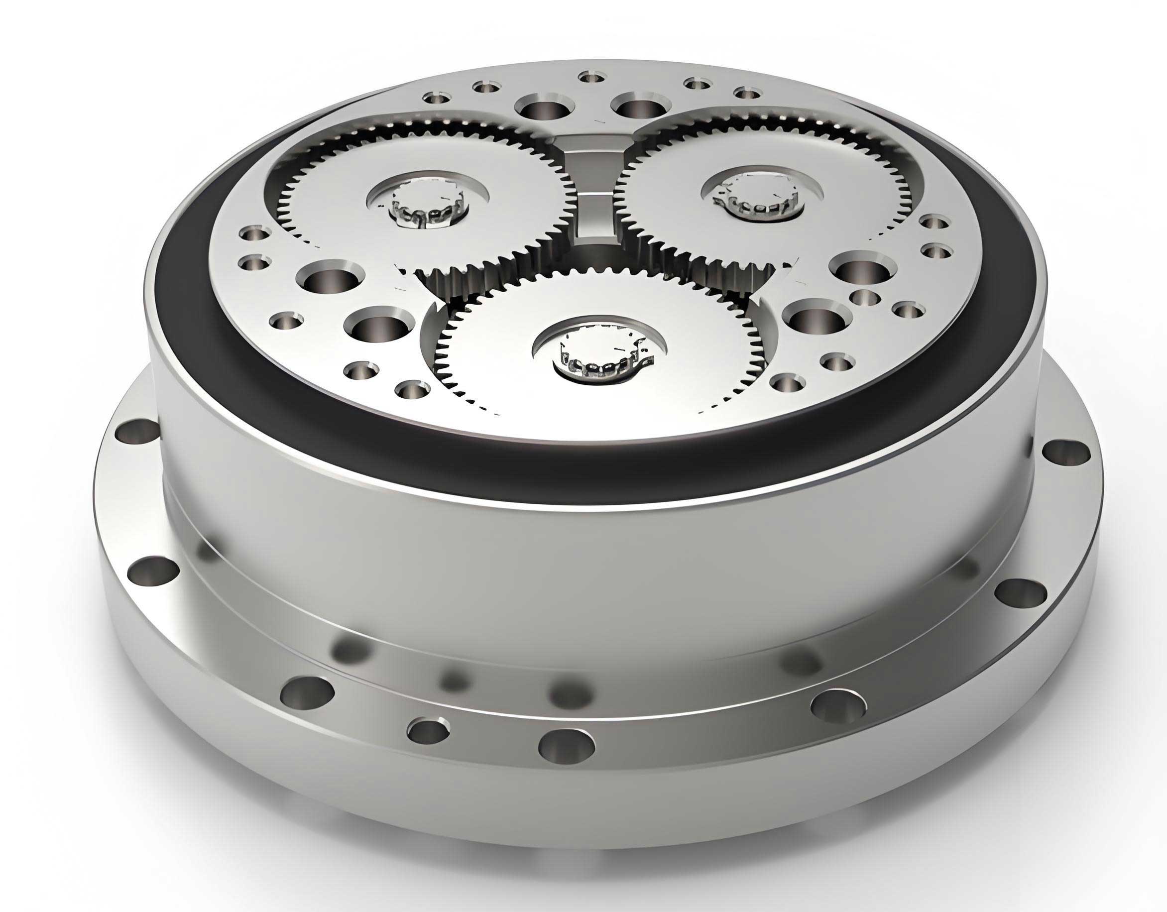
The rotary vector reducer, often abbreviated as RV reducer, is a two-stage planetary transmission device that combines a primary involute planetary gear stage with a secondary cycloidal pin-wheel stage. This unique architecture is what grants the rotary vector reducer its superior attributes. The first stage involves a sun gear, planetary gears, and a carrier, while the second stage comprises cycloidal discs, pin gears, and a pin housing. A critical component linking these stages is the crankshaft, which transmits motion and torque. Understanding the fundamental operating principle is essential for any design endeavor. In essence, power is input to the sun gear, which drives the planetary gears in the first stage. The planetary gears are mounted on crankshafts, and these crankshafts then drive the cycloidal discs. The cycloidal discs engage with the stationary pin gears housed in the pin housing, causing the discs to undergo a compound motion of revolution and rotation. This motion is finally output through the carrier or housing, resulting in a greatly reduced speed and amplified torque. The kinematic relationship defines the overall reduction ratio, which is a function of the tooth counts from both stages. The complexity arises from the need to satisfy multiple interdependent geometric, kinematic, and strength constraints simultaneously during the gear tooth selection, or “gear matching,” process. A precise and efficient gear matching calculation is the first critical step in designing a reliable rotary vector reducer.
The automatic gear calculation program I developed is grounded in a set of five fundamental conditions that any valid tooth number combination for a rotary vector reducer must satisfy. These conditions ensure proper kinematic function, structural integrity, and load distribution. For the RV-110E case study, the initial parameters are: rated power \( P = 2.26 \, \text{kW} \), output speed \( n = 15 \, \text{r/min} \), target transmission ratio \( i_p = 111 \), and gear module \( m = 1.25 \, \text{mm} \). The five conditions are as follows:
1. Transmission Ratio Condition: The actual transmission ratio \( i \) of the rotary vector reducer, with the pin housing fixed, is given by:
$$ i = 1 + \frac{Z_2}{Z_1} \cdot Z_5 $$
where \( Z_1 \) is the sun gear tooth number, \( Z_2 \) is the planetary gear tooth number, and \( Z_5 \) is the pin gear tooth number. The calculated ratio must fall within an acceptable error margin \( \Delta i_p \) of the target ratio \( i_p \):
$$ \left| \frac{i – i_p}{i_p} \right| \leq \Delta i_p $$
Typically, \( \Delta i_p \) is chosen between 0.01 and 0.04.
2. Undercutting Avoidance Condition: To prevent gear tooth undercutting in the involute stage, which weakens the tooth root and harms meshing quality, the sun gear must have a minimum number of teeth:
$$ Z_1 \geq 17 $$
3. Load Distribution Condition: To prevent excessive torque input into the second cycloidal stage, the tooth number ratio between the planetary and sun gears in the first stage is constrained:
$$ \frac{Z_2}{Z_1} \geq 1.5 $$
This ensures a balanced torque split between the two reduction stages of the rotary vector reducer.
4. One-Tooth Difference Condition: In the cycloidal stage, a fundamental requirement is that the pin gear tooth number \( Z_5 \) must be an even number and must exceed the cycloidal disc tooth number by exactly one. This is inherent to the cycloidal mechanism’s operation.
5. Structural Dimension Condition: The center distance \( a_0 \) between the sun and planetary gears in the first stage must be proportional to the pin gear center circle radius \( R_p \) of the second stage to ensure proper force transmission through the crankshafts:
$$ a_0 = (0.5 \sim 0.6) R_p $$
The radius \( R_p \) is estimated from the output torque \( T \), which itself depends on the efficiency \( \eta \) of the rotary vector reducer:
$$ T = 9,550,000 \cdot \frac{P}{n} \cdot \eta $$
$$ R_p = (0.85 \sim 1.3) \sqrt[3]{T} $$
The overall efficiency \( \eta \) is a product of gear mesh efficiencies and bearing efficiencies:
$$ \eta = \eta_{16} \cdot \eta_B $$
$$ \eta_B = \eta_{B1} \cdot \eta_{B2} \cdot \eta_{B3} $$
where \( \eta_{B1}, \eta_{B2}, \eta_{B3} \) are bearing efficiencies (typically 0.99 each). The gear transmission efficiency \( \eta_{16} \) is more complex, involving the efficiencies of both stages:
$$ \eta_{16} = \frac{ \left( \frac{Z_5}{Z_4} – 1 \right) \left( \frac{Z_5}{Z_4} – \eta_{H6} \right) + \frac{Z_2}{Z_1} \cdot \frac{Z_5}{Z_4} \cdot \eta_{H1} }{ \left( \frac{Z_5}{Z_4} – \eta_{H6} \right) \left( \frac{Z_5}{Z_4} – 1 \right) + \frac{Z_2}{Z_1} \cdot \frac{Z_5}{Z_4} } $$
Here, \( Z_4 \) is the cycloidal disc tooth number (where \( Z_5 = Z_4 + 1 \)), \( \eta_{H1} \) is the involute gear pair efficiency (~0.992), and \( \eta_{H6} \) is the cycloidal mesh efficiency (~0.998).
I implemented an algorithm based on these conditions using the VB.NET programming language within the Visual Studio 2022 integrated development environment. The program logic involves iterating through plausible integer values for \( Z_1 \) and \( Z_2 \), calculating \( Z_5 \) from the transmission ratio equation, and then checking all other constraints. The workflow is summarized in the following algorithmic steps:
Step 1: Input the four key parameters: \( P, i_p, m, n \).
Step 2: Begin iteration for \( Z_1 \) starting from the minimum value of 17.
Step 3: For each \( Z_1 \), iterate \( Z_2 \) such that the ratio \( Z_2/Z_1 \geq 1.5 \).
Step 4: For each \( (Z_1, Z_2) \) pair, calculate the required \( Z_5 \) from the transmission ratio formula: \( Z_5 = (i_p – 1) \cdot Z_1 / Z_2 \). Since \( Z_5 \) must be an integer, the program rounds it to the nearest whole number and checks the evenness condition.
Step 5: With a candidate \( Z_5 \), compute the actual transmission ratio \( i \) and verify the error margin condition.
Step 6: Calculate the output torque \( T \) and center distance conditions using the efficiency formulas, ensuring \( a_0 \) falls within the specified range relative to \( R_p \).
Step 7: If all conditions are satisfied, record the valid combination \( (Z_1, Z_2, Z_5, i, T, \eta) \).
Step 8: Continue iterations until a sufficient number of combinations are found or search limits are reached.
The program features a graphical user interface (GUI) that allows for easy parameter input and displays results in a structured format. Upon execution for the RV-110E parameters, the program generated multiple valid gear tooth combinations. A subset of these results is presented in the table below to illustrate the output. The comprehensive results aid the designer in selecting an optimal set based on secondary criteria like compactness, efficiency, or manufacturing considerations.
| Set No. | Sun Gear Teeth \( Z_1 \) | Planetary Gear Teeth \( Z_2 \) | Pin Gear Teeth \( Z_5 \) | Efficiency \( \eta \) | Output Torque \( T \) (N·m) | Actual Ratio \( i \) |
|---|---|---|---|---|---|---|
| 1 | 17 | 59 | 32 | 0.907 | 1304.526 | 112.059 |
| 2 | 18 | 62 | 32 | 0.907 | 1304.532 | 111.222 |
| 3 | 19 | 62 | 34 | 0.903 | 1299.679 | 111.947 |
| 4 | 19 | 70 | 46 | 0.883 | 1270.952 | 170.474 |
| 5 | 20 | 55 | 40 | 0.892 | 1278.000 | 111.000 |
| 6 | 20 | 69 | 46 | 0.883 | 1271.001 | 159.700 |
| 7 | 21 | 68 | 34 | 0.903 | 1299.685 | 111.095 |
| 8 | 22 | 61 | 40 | 0.893 | 1285.350 | 111.909 |
| 9 | 22 | 72 | 34 | 0.903 | 1299.676 | 112.273 |
| 10 | 22 | 68 | 46 | 0.883 | 1271.092 | 143.182 |
| 11 | 23 | 75 | 34 | 0.903 | 1299.679 | 111.870 |
| 12 | 23 | 66 | 46 | 0.883 | 1271.159 | 133.000 |
| 13 | 24 | 58 | 46 | 0.884 | 1271.334 | 112.167 |
| 14 | 24 | 78 | 34 | 0.903 | 1299.682 | 111.500 |
| 15 | 24 | 65 | 46 | 0.883 | 1271.215 | 125.583 |
| 16 | 25 | 69 | 40 | 0.893 | 1285.355 | 111.400 |
| 17 | 25 | 81 | 34 | 0.903 | 1299.685 | 111.160 |
| 18 | 25 | 82 | 34 | 0.903 | 1299.674 | 112.520 |
| 19 | 25 | 70 | 46 | 0.883 | 1271.182 | 129.800 |
| 20 | 25 | 69 | 46 | 0.883 | 1271.196 | 127.960 |
| 21 | 25 | 68 | 46 | 0.883 | 1271.211 | 126.120 |
| 22 | 25 | 64 | 46 | 0.884 | 1271.272 | 118.760 |
| 23 | 26 | 84 | 34 | 0.903 | 1299.687 | 110.846 |
| 24 | 26 | 85 | 34 | 0.903 | 1299.677 | 112.154 |
| 25 | 27 | 65 | 46 | 0.884 | 1271.339 | 111.741 |
From the table, it is evident that numerous valid configurations exist. For a rotary vector reducer targeting a ratio near 111, sets like 3, 7, 10, 12, 13, 15, 20, 21, and 22 offer practical solutions, balancing transmission ratio accuracy, efficiency, and load distribution. The automatic program thus eliminates the tedious manual trial-and-error process, providing a robust foundation for the initial design phase of any rotary vector reducer.
However, selecting gear tooth numbers is only the first step. The gears must withstand the operational loads without failure. Therefore, I developed a second program module dedicated to the strength calibration of the involute gears (sun gear and planetary gears) within the rotary vector reducer. This module performs both bending fatigue strength and contact fatigue strength checks according to standardized gear design principles. The formulas are implemented with appropriate adjustment factors to account for the specific operating conditions of a rotary vector reducer.
For tooth root bending fatigue strength, the criterion is that the calculated bending stress \( \sigma_F \) must not exceed the permissible bending stress \( \sigma_{FP} \):
$$ \sigma_F \leq \sigma_{FP} $$
The calculation involves several factors:
$$ \sigma_F = \frac{F_t}{b m} K_A K_V K_{F\beta} K_{F\alpha} K_{Fp} Y_{Fa} Y_{Sa} Y_{\epsilon} Y_{\beta} $$
Where:
- \( F_t \) is the nominal tangential force at the reference circle.
- \( b \) is the face width of the gear.
- \( m \) is the module.
- \( K_A \) is the application factor (accounting for external load characteristics).
- \( K_V \) is the dynamic factor (accounting for internal dynamic loads).
- \( K_{F\beta} \) is the face load factor for bending strength.
- \( K_{F\alpha} \) is the transverse load factor for bending strength.
- \( K_{Fp} \) is the planetary load sharing factor (critical for the planetary stage in a rotary vector reducer).
- \( Y_{Fa} \) is the form factor (depends on tooth geometry and number).
- \( Y_{Sa} \) is the stress correction factor.
- \( Y_{\epsilon} \) is the contact ratio factor.
- \( Y_{\beta} \) is the helix angle factor (for straight gears, often 1).
The permissible stress is derived from the material’s endurance limit and various modifying factors:
$$ \sigma_{FP} = \frac{\sigma_{F \lim}}{S_{F \min}} Y_{ST} Y_{NT} Y_{\delta relT} Y_{R relT} Y_X $$
Where:
- \( \sigma_{F \lim} \) is the nominal bending fatigue limit of the material.
- \( S_{F \min} \) is the minimum required safety factor.
- \( Y_{ST} \) is the stress correction factor for the test specimen.
- \( Y_{NT} \) is the life factor for bending strength.
- \( Y_{\delta relT} \) is the relative notch sensitivity factor.
- \( Y_{R relT} \) is the relative surface condition factor.
- \( Y_X \) is the size factor.
For tooth flank contact fatigue strength (pitting resistance), the criterion is:
$$ \sigma_H \leq \sigma_{HP} $$
The calculated contact stress \( \sigma_H \) is given by:
$$ \sigma_H = Z_H Z_E Z_{\epsilon} Z_{\beta} \sqrt{ \frac{F_t}{d b} \cdot \frac{u \pm 1}{u} \cdot K_A K_V K_{H\beta} K_{H\alpha} K_{Hp} } $$
Where:
- \( Z_H \) is the zone factor (accounts for tooth flank curvature at the pitch point).
- \( Z_E \) is the elasticity factor (combines material properties of both gears).
- \( Z_{\epsilon} \) is the contact ratio factor.
- \( Z_{\beta} \) is the helix angle factor.
- \( d \) is the reference diameter of the pinion (sun gear in this case).
- \( u \) is the gear ratio \( Z_2 / Z_1 \).
- \( K_{H\beta} \) is the face load factor for contact stress.
- \( K_{H\alpha} \) is the transverse load factor for contact stress.
- \( K_{Hp} \) is the planetary load sharing factor for contact stress.
The permissible contact stress \( \sigma_{HP} \) is:
$$ \sigma_{HP} = \frac{\sigma_{H \lim}}{S_{H \min}} Z_{NT} Z_L Z_V Z_R Z_W Z_X $$
Where:
- \( \sigma_{H \lim} \) is the nominal contact fatigue limit of the material.
- \( S_{H \min} \) is the minimum required safety factor.
- \( Z_{NT} \) is the life factor for contact stress.
- \( Z_L \) is the lubricant factor.
- \( Z_V \) is the velocity factor.
- \( Z_R \) is the roughness factor.
- \( Z_W \) is the work hardening factor.
- \( Z_X \) is the size factor for contact stress.
I integrated these equations into a VB.NET program with a dedicated interface. The user inputs the gear geometry (from the gear calculation results), material properties, lubrication conditions, and operational parameters. The program then computes all necessary factors, retrieves appropriate coefficients from embedded databases or empirical formulas, and performs the strength checks. For demonstration, I applied the strength calibration to gear set number 5 from the table above (\( Z_1 = 20, Z_2 = 55 \)), assuming standard alloy steel for gears, proper lubrication, and the operational parameters of the RV-110E rotary vector reducer. The program output confirms that for both the sun gear and the planetary gear, the calculated bending and contact stresses are well below the permissible limits, indicating a safe design. The interface presents the results clearly, showing intermediate calculation steps and final safety factors. This automated strength check provides immediate feedback on the viability of a chosen gear set from the gear matching program, closing the design loop efficiently. Without such automation, verifying each potential gear combination would be prohibitively time-consuming, highlighting the value of this integrated computational approach for rotary vector reducer design.
The development and application of these automated programs demonstrate a significant advancement in the methodology for designing rotary vector reducers. The gear calculation program systematically explores the design space defined by the five fundamental conditions, generating a palette of valid solutions that a designer can evaluate based on secondary objectives. This replaces an error-prone manual process that often relies on experience and guesswork. The strength calibration program then provides a rigorous and rapid verification of the mechanical integrity of the selected gears, ensuring reliability before detailed manufacturing drawings are produced. Together, these tools form a cohesive parameterized design framework that can be adapted to various models and specifications of rotary vector reducers. By encapsulating complex engineering formulas and logic into user-friendly software, I have effectively reduced the barrier to efficient and accurate design. The case study of the RV-110E rotary vector reducer confirms the practicality and effectiveness of the approach. Future work could extend this parameterization to other components of the rotary vector reducer, such as the cycloidal disc profile optimization, bearing selection, or housing design, creating a comprehensive digital design suite. Furthermore, integrating these programs with CAD and FEA software could enable a fully automated design-to-analysis workflow, pushing the boundaries of rotary vector reducer performance and innovation. In conclusion, the automated gear calculation and strength calibration programs presented herein offer a robust solution to accelerate the development cycle, enhance design quality, and reduce costs for rotary vector reducers, contributing to the broader advancement of precision transmission technology in robotics and automation.