
In my experience as an engineer involved in gear manufacturing, I have always been fascinated by the complexities of gear cutting, especially for spiral bevel gears. The traditional manual methods for calculating cutting adjustments are not only time-consuming but also prone to errors, which can severely impact the quality and performance of the final product. Design automation, often seen as the initial phase of Computer-Aided Design (CAD), offers a transformative solution. By inputting performance and specification requirements as raw data into a computer, the entire design process can be automated through pre-programmed routines, ultimately outputting the necessary data for production. This approach is crucial for enhancing design speed and precision, meeting the demands for shorter product development cycles. The key to achieving this lies in adopting design automation technology, with a particular focus on gear cutting computations.
When developing automated applications for gear cutting, reliability and speed are paramount, followed by user-friendliness and a high degree of automation. Based on my extensive work in this field, I have identified several critical principles for programming such systems. First, diagnostic measures must be implemented to verify program correctness. Ensuring that the program is error-free is a prerequisite for automated computation in gear cutting. Second, a modular structure should be preferred over nested structures. This facilitates easier modification and expansion of the code, which is essential as gear cutting requirements evolve. Third, algorithms should be used to replace stored charts and tables whenever possible. This not only simplifies the program and saves memory but also reduces input workload and enhances calculation accuracy—a vital aspect for precise gear cutting. Finally, incorporating necessary human-computer interaction features is essential. Terminal displays and print outputs should utilize both text and numerical data to improve usability.
Applying these principles, I developed a comprehensive program package for automating the cutting adjustment computations of spiral bevel gears. Gear cutting, especially for spiral bevel gears, involves intricate adjustments of the cutter and machine settings, making it one of the most challenging aspects of gear manufacturing. The urgency to integrate design automation to boost speed and accuracy motivated this project. The program package consists of multiple interconnected modules, all written in a high-level algorithmic language, capable of running on microcomputers to compute adjustment data for both the cutter and the gear cutting machine during tooth machining.
The control center of this system is a main control program that orchestrates the activation of various functional programs. All programs adhere to a modular architecture, divided into main programs and common subroutines. The common subroutines are subordinate to the main programs and can be conveniently called upon when needed. This hierarchical and clear structure makes the system easy to debug, maintain, modify, port, and expand. The workflow begins with the main control program displaying a functional menu in a user-friendly interface. Based on the operator’s selection, it loads and initiates the corresponding functional program. The functional program then displays its content and initializes coefficients and constants from charts. Following this, a self-diagnostic routine runs: it performs a trial calculation with a predefined set of parameters, computes a cumulative sum, and compares it against a standard value. If discrepancies arise, the program halts and notifies the operator; if consistent, it proceeds to prompt for input items.
The operator is then guided to input seven key original parameters for a pair of spiral bevel gears. The program validates this data; if errors are detected or values fall outside permissible ranges, it requests re-input. Once validated, the computation phase begins. After calculations, the main program invokes a printing subroutine to output the results. The system then returns to a waiting state, ready for the next set of gear parameters, enabling continuous operation. This streamlined process significantly enhances efficiency in gear cutting tasks.
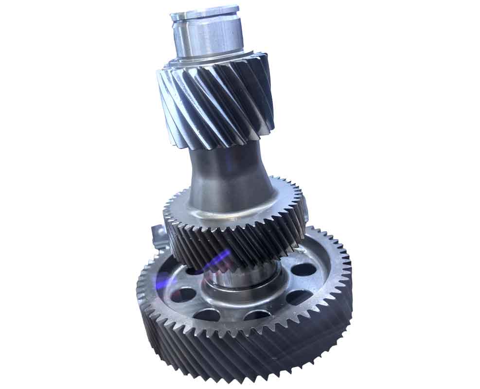
To illustrate the practical application, consider an example involving a pair of mating spiral bevel gears used in a keyway milling machine. The goal is to process these gears on a specific gear cutting machine using the single-side double-side method. The operator inputs the seven original parameters via the keyboard, and the system automatically generates a comprehensive adjustment table for the gear cutting machine. This entire gear cutting computation, which would take a skilled technician approximately three days manually, is completed by the microcomputer in just seven seconds. Moreover, the accuracy surpasses that of manual calculations, addressing issues like slow speed, low precision, non-standardization, and computational errors. This automation not only liberates engineers from repetitive tasks but also elevates their role to more creative and judgment-intensive activities.
In gear cutting, particularly for spiral bevel gears, the computations involve numerous geometric and kinematic parameters. Key formulas are essential for determining adjustments. For instance, the cutter radius \( R_c \) can be derived from the pitch diameter \( d \) and pressure angle \( \alpha \) using:
$$ R_c = \frac{d}{2 \sin \alpha} $$
This is critical in setting up the cutter for accurate gear cutting. Another important aspect is the spiral angle \( \beta \), which influences the tooth contact pattern. The relationship between the spiral angle and other parameters can be expressed as:
$$ \tan \beta = \frac{\pi d}{P} $$
where \( P \) is the circular pitch. For gear cutting depth \( h \), a common formula based on module \( m \) is:
$$ h = 2.25 \cdot m $$
ensuring proper tooth depth during machining. Additionally, the machine settings such as the cradle angle \( \theta_c \) and cutter tilt \( \phi_t \) are calculated using iterative algorithms that consider gear geometry and cutting method. These computations are integral to the automation process, allowing for precise gear cutting adjustments.
The input parameters for a typical gear cutting computation are summarized in the table below, which includes data for both the pinion and gear. These parameters serve as the foundation for all subsequent calculations in the gear cutting process.
| Input Item | Pinion | Gear |
|---|---|---|
| Number of Teeth | 15 | 45 |
| Module (mm) | 4.5 | 4.5 |
| Pressure Angle (degrees) | 20 | 20 |
| Spiral Angle (degrees) | 35 | 35 |
| Hand of Spiral | Right | Left |
| Face Width (mm) | 40 | 40 |
| Cutting Method | Single-Side Double-Side | |
Based on these inputs, the automated system computes various adjustment settings for the gear cutting machine. The output includes critical parameters that ensure accurate tooth formation during gear cutting. Below is a simplified adjustment table generated by the program, showcasing key values for machine setup.
| Adjustment Item | Rough Cutting | Finish Cutting (Concave) | Finish Cutting (Convex) |
|---|---|---|---|
| Cradle Angle (degrees) | 125.6 | 130.2 | 120.8 |
| Cutter Tilt (degrees) | 3.5 | 3.8 | 3.2 |
| Feed Rate (mm/min) | 150 | 100 | 100 |
| Depth of Cut (mm) | 10.125 | 2.25 | 2.25 |
| Cutter Radius (mm) | 76.5 | 76.5 | 76.5 |
These adjustments are derived through complex algorithms that optimize the gear cutting process. For example, the cradle angle \( \theta_c \) is calculated using the formula:
$$ \theta_c = \arcsin\left(\frac{m \cdot z}{2 R_c}\right) + \Delta \theta $$
where \( z \) is the number of teeth, \( m \) is the module, \( R_c \) is the cutter radius, and \( \Delta \theta \) is a correction factor based on spiral angle and cutting method. Similarly, the cutter tilt \( \phi_t \) ensures proper tooth flank contact and is given by:
$$ \phi_t = \beta – \alpha \cdot k_t $$
where \( k_t \) is a tilt coefficient determined empirically. The feed rate and depth of cut are optimized to balance efficiency and tool life in gear cutting operations.
Furthermore, the program incorporates iterative methods to refine these values. For instance, the forming diameter \( D_f \), which affects tooth profile accuracy, is computed as:
$$ D_f = d + 2 \cdot m \cdot \cos \beta $$
This is crucial for setting the machine’s workpiece position. Another key parameter is the offset or sliding base displacement \( S_b \), used to adjust the cutter path, calculated by:
$$ S_b = R_c \cdot \sin \phi_t + C_o $$
where \( C_o \) is an offset constant from machine geometry. These formulas highlight the mathematical rigor involved in automating gear cutting computations.
The benefits of this automation extend beyond mere speed. In gear cutting, consistency is vital for mass production. The program ensures that every gear pair is computed with identical precision, reducing variability. Additionally, the modular design allows for easy updates; for example, if a new cutter type is introduced, only relevant modules need modification without disrupting the entire system. This adaptability is essential in evolving manufacturing environments where gear cutting techniques continuously advance.
From a broader perspective, the integration of such automation in gear cutting aligns with Industry 4.0 trends, where digital twins and real-time adjustments become commonplace. The program can be extended to include sensor feedback for adaptive control, further enhancing gear cutting accuracy. For example, real-time monitoring of tool wear could dynamically adjust cutting parameters using algorithms like:
$$ F_{adj} = F_0 \cdot e^{-k_w t} $$
where \( F_{adj} \) is the adjusted feed rate, \( F_0 \) is the initial feed, \( k_w \) is a wear coefficient, and \( t \) is cutting time. This proactive approach minimizes errors and extends tool life in gear cutting operations.
In conclusion, the automation of spiral bevel gear cutting computation represents a significant leap forward in manufacturing technology. By embracing design automation principles—diagnostic checks, modular structures, algorithmic replacements, and intuitive interfaces—we can achieve remarkable improvements in speed, precision, and reliability. The example detailed here demonstrates how a microcomputer can perform in seconds what once took days, revolutionizing the gear cutting process. This not only frees engineers from tedious calculations but also empowers them to engage in higher-level innovation. As gear cutting demands grow more complex, such automated systems will become indispensable, driving efficiency and quality in gear production worldwide.