When considering the deformation of gear teeth under load, the basic meshing equation shall be rewritten as:

Δ r2、 Δ R1 – deformation of gear tooth itself;
Δ n2、 Δ N1 – normal vector increment caused by tooth deformation;
The key of tooth load contact analysis is to reveal the meshing mechanism of gear pair during load transmission and comprehensively analyze the influence of various deformations in gear pair on meshing performance. For the convenience of analysis, the deformation of gear pair under load is divided into two parts: one is the deformation of gear pair support system, the other is the deformation of gear tooth itself.
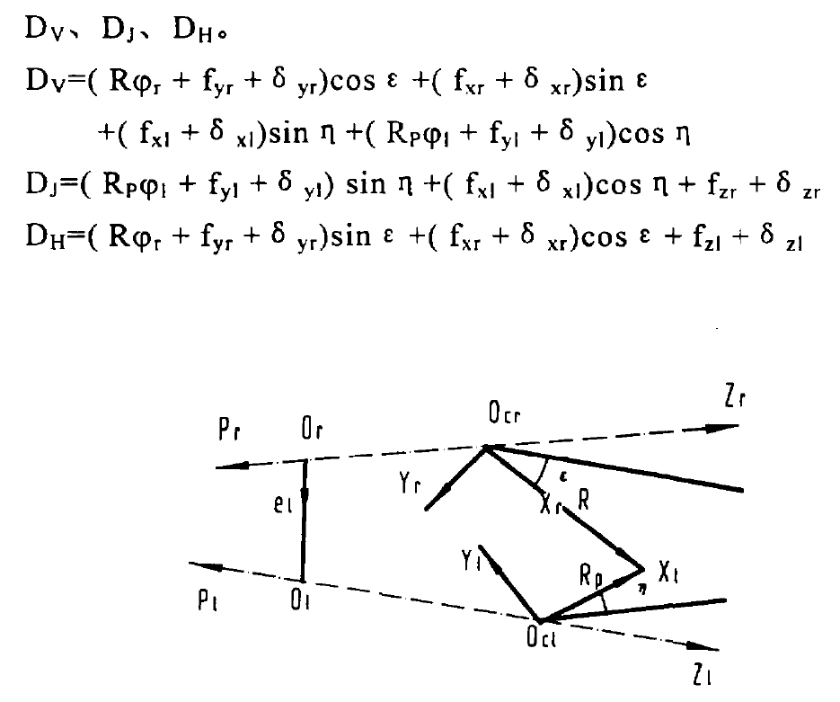
The elastic deformation of the gear pair support system mainly refers to the elastic deformation of the support shaft and the elastic deformation of the support bearing. To describe these deformations or displacements, a coordinate system as shown in the figure is established. The coordinate system {OCR, XR, yr, Zr} is established on the large wheel support shaft. The direction of the XR axis points to the meshing point from the origin, and the direction of the Zr axis points to the large end from the small end of the gear along the axis. The coordinate system on the corresponding small wheel support shaft is {OC1, x1, Y1, Z1}. In the figure, PR and P1 are the unit vectors on the axis of the large and small wheels respectively, and E1 is the offset direction. Now, the deformations of the supporting shafts of large and small wheels are recorded as: torsional deformation φ r, φ 1. Axial deformation FZR, FZ1, bending deformation FXR, FYR and FX1, FY1. Record the displacement of the large and small wheel support shaft along the coordinate axis as follows: δ zr, δ xr, δ Yr and δ z1, δ x1, δ y1。
The TCA of no-load or light load spiral bevel gear contact analysis is carried out under the premise that the installation adjustment values V0, J0 and H0 are given and the gear and its support system are rigid. When the supporting system is deformed, the relative position of the meshing tooth surface in space will change. Therefore, the concept of load equivalent installation adjustment values V, J and H is proposed. That is, the deformation of the gear pair support system with the change of the relative position of the meshing tooth surface caused by the load is regarded as the change of the installation adjustment values V, J and H. The change of this set of installation adjustment values V, J and H is called load equivalent installation adjustment values V, J and h, which are recorded as DV, DJ and DH.

Where:
R – radius of meshing point of large wheel;
RP – radius of meshing point of small wheel;
ε,η— Are the offset angles of large and small wheel nodes respectively.
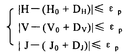
The tooth surface contact area is composed of many instantaneous contact ellipses. The pressure center line of each instantaneous contact ellipse is the contact trace. The pressure center depends on the theoretical meshing point after loading. Using the concept of load equivalent, the numerical iterative equation for solving the theoretical meshing point after loading can be established.

Where: ε P-convergence accuracy
The deformation of the gear tooth itself is obtained by the finite element method. here τ Become τ+Δτ, among Δτ From the formula.
