
Define point G as the starting point of the involute tooth profile, point K as the end point of the involute tooth profile, and point Gb as the intersection point of the involute and the base circle. Figure 1 shows a traditional potential energy method for solving a time-varying meshing stiffness spur gear tooth model. In Figure 1, KG is an involute tooth profile; GH is the transitional curve tooth profile of the tooth root; RG, rf, and rb are the initial circle radius, root circle radius, and base circle radius of the involute tooth profile, respectively. The calculation formula is:
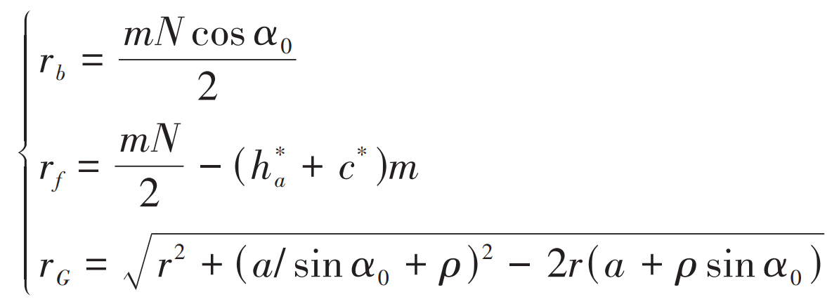
In the formula, m is the modulus; N is the number of teeth; α 0 is the pressure angle; H * a, c * are the coefficient of tooth top height and the coefficient of tooth top clearance, respectively.
According to the formula, for standard involute cylindrical spur gears, it can be theoretically obtained that when the number of teeth is equal to 17 At 10 o’clock, rG=rb; When the number of teeth equals 41 At 25, rf=rb. When the number of teeth in a spur gear is small, the starting point G of the involute tooth profile basically coincides with the intersection point Gb of the involute tooth profile and the base circle, and the difference between rG and rb is not significant, which has little impact on the calculation results of time-varying meshing stiffness.

As shown in Figure 2, as the number of teeth in the spur gear gradually increases, the starting point Gb of the involute tooth profile on the base circle gradually moves away from the starting point G of the involute tooth profile. Especially when the number of teeth is greater than 41, the base circle is already located inside the tooth root circle. As can be seen from Figure 2, there is a significant difference between rG and rb. The traditional time-varying meshing stiffness calculation method based on the potential energy method does not consider that when the number of teeth is greater than 41, the actual starting point of the involute tooth profile changes due to the separation of point Gb and point G, and the point Gb in Figure 2 is still used as the starting point of the involute tooth profile, which inevitably leads to errors in the time-varying meshing stiffness calculation.
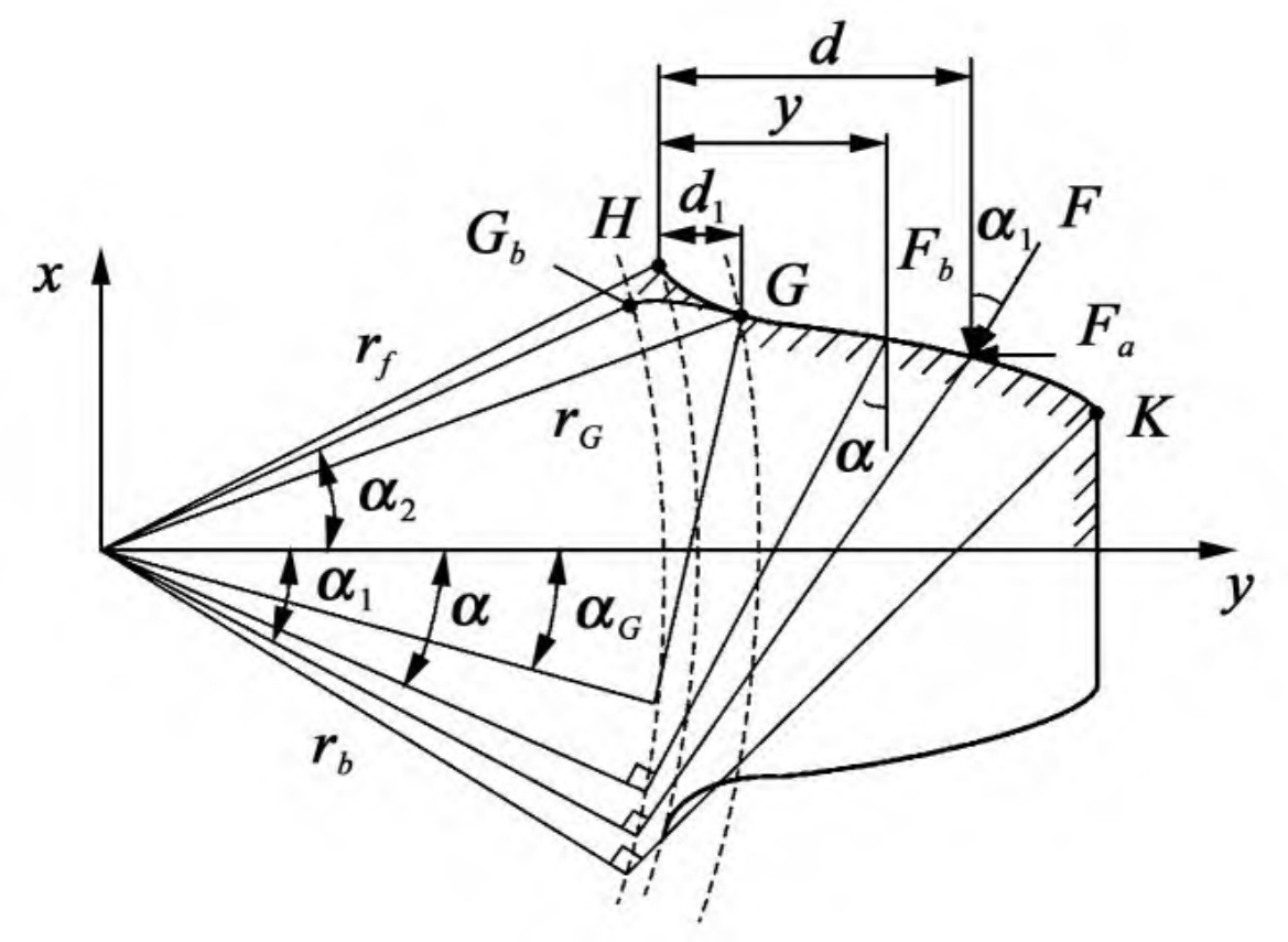
It can be seen from Figure 1 and Figure 2 that when the number of teeth is greater than 41, due to the separation of point Gb and point G, the pressure angle at the starting point G of the actual involute profile of the spur gear teeth changes from α 2 becomes α G。 As mentioned earlier, the KGb segment meets the geometric characteristics of involutes, so the meanings of the parameters in Figure 2 are identical to those in Figure 1. It should be noted that due to changes in the involute tooth profile, the radius of the circle where the point G is located is the radius rG of the initial circle of the involute tooth profile.