Taking right-hand rotation as an example, the coordinate system for the forming of face gear spherical hob based worm is established, as shown in the figure. In the figure: S0 (x0, Y0, Z0) is a fixed coordinate system; Sn0 (xn0, yn0, Zn0) is that S0 rotates around the x0 axis λ The auxiliary fixed coordinate system obtained after the angle; SW (XW, YW, ZW) is the dynamic coordinate system fixedly connected with the spherical hob base worm of face gear; The ZW rotation angle is set to φ w ; Sn (xn, YN, Zn) is the motion coordinate system fixedly connected with the cutting tool; Set the rotation angle around yn to φ 0 φ W and φ 0 has the following kinematic relationships:
The transformation matrices are as follows:
MW, 0 is the conversion matrix from S0 to SW, and the expression is
Μ 0, N0 is the conversion matrix from sn0 to S0, and the expression is
Μ N0, n is the conversion matrix from SN to sn0, and the expression is
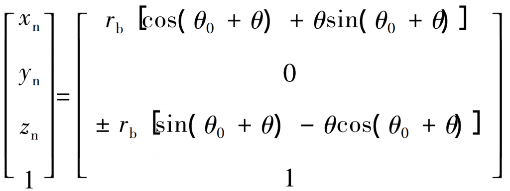
In Sn, the involute equation is expressed as


