
For the calculation of heavy load large module gear and rack drive, there are many literature research calculation methods, some use integral method, some use mapping function method. In the calculation method of gear root bending stress, the bending section is more accurate than the tooth root stress calculated by plane section, but the calculation method of bending section is too complex. The plane section method using ISO 30 ° tangent to determine the dangerous section is simple, And the test shows that the difference of tooth root stress calculated by the two methods is not more than 5%~6%. For the large module gear rack with low speed and heavy load, special tools and processing methods are used when machining, and there is no special calculation software at present. Most of them are calculated by the finite element analysis method. The finite element calculation process is complex and must be modeled and analyzed, which is not conducive to the initial parameter design. A fast analytical calculation method for the strength of large module gear rack is studied to facilitate the design and calculation.
Special attention is paid here to whether the tooth root stress is calculated according to the single tooth meshing stress point or the tooth tip meshing stress point. When the gear accuracy is high, the tooth root stress is calculated according to the single tooth meshing point; When the gear accuracy is low, which method to calculate the tooth root stress is determined according to the load distribution coefficient Ka.
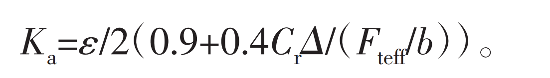
Where: Cr is the average value of the superimposed stiffness coefficient of two pairs of gear teeth engaged at the same time; Δ Is the base pitch difference of two gears; ε Is the coincidence degree; Fteff is the circumferential force on the indexing circle of gear teeth, Fteff=F · t KA · Kv · KB; B is the tooth width.
When Ka ≤ 1, it indicates that the force on the single tooth stress point of the gear is maximum; When Ka ≥ 1, it means that all loads transmitted by the gear act on the tooth top, and the tooth root stress is calculated according to the force on the tooth top.
The manufacturing accuracy of large module gear racks with low speed and heavy load is difficult to guarantee. Even if the overlap coefficient of the gear rack mesh is greater than 1.2, the force on the single tooth is applied during the load transfer process of the teeth, so the tooth root stress should be calculated according to the load on the top of the tooth, and the tooth root stress cannot be calculated according to the load on the single tooth mesh point. When the gear accuracy is lower than Grade 11, the tooth root stress shall be calculated according to the tooth top stress.
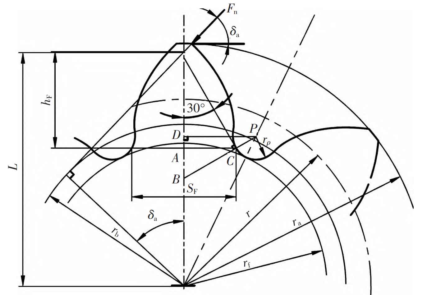
The tooth root stress calculation method of large module gear rack specially used for low speed and heavy load is deduced according to Figure 1 and Figure 2.
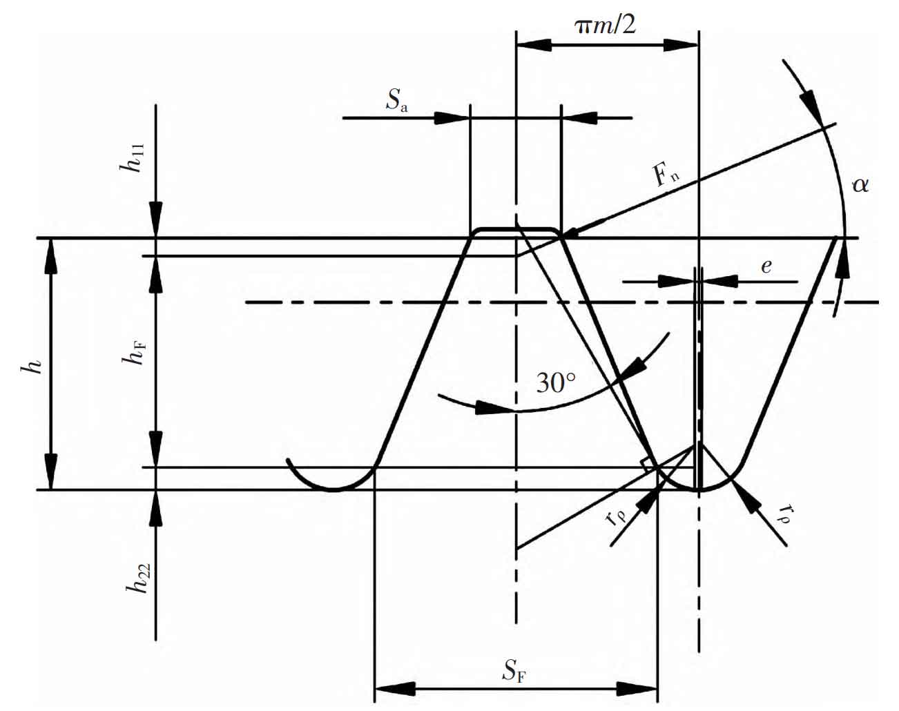
According to the 30 ° tangent line of ISO, the plane section method (as shown in Figure 1) is used to determine the dangerous section. The tooth root stress calculation formula is:
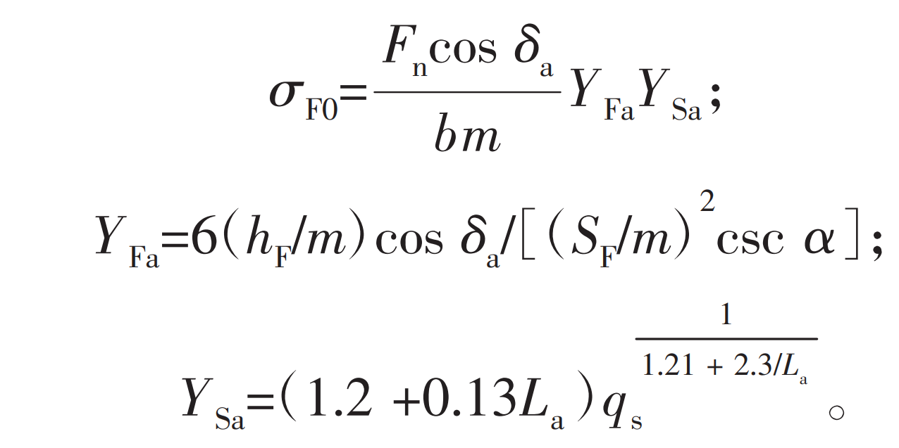
In the formula, the width SF of the dangerous section and the force arm hF are the key parameters for calculation. The following two parameters are derived respectively according to the gear and rack.