
I investigate the bending stress behavior of tooth roots in multi-modulus involute worm and helical gear pairs. In contrast to conventional worm and worm gear drives, a worm and helical gear transmission offers simpler design, easier manufacturing, improved lubrication, and lower sensitivity to assembly errors. These advantages make it attractive for automotive transmissions, power tools, smart home devices, and many other motion and power transmission systems. Among the possible failure modes, fatigue fracture at the tooth root of the helical gear is one of the most critical. However, for a worm and helical gear pair in which the normal module and normal pressure angle of the worm are not equal to those of the helical gear, the tooth root stress characteristics have remained unclear. Therefore, I focus on the influence of the modulus ratio on the tooth root bending stress of both the worm and the helical gear. The final aim is to provide a theoretical basis for improving the service life and load-carrying capacity of such transmissions.
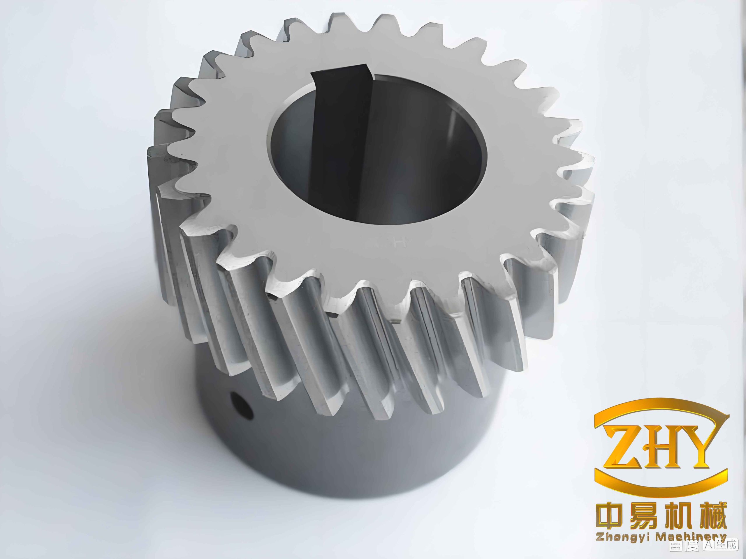
I begin with the correct meshing condition. For a worm and helical gear pair, the axial pitch of the worm on the intermediate plane must equal the transverse pitch of the helical gear, and the two members must have the same hand of helix. For a multi-modulus pair, I express the condition in terms of normal module and normal pressure angle. The fundamental relation is
$$m_{n1}\cos\alpha_{n1}=m_{n2}\cos\alpha_{n2}$$
where \(m_{n1}\) and \(m_{n2}\) are the normal modules of the worm and the helical gear, respectively, and \(\alpha_{n1}\) and \(\alpha_{n2}\) are their normal pressure angles. Equivalently, I obtain
$$\frac{m_{n1}}{m_{n2}}=\frac{\cos\alpha_{n2}}{\cos\alpha_{n1}}$$
In addition, the lead angle of the worm \(\gamma\) must equal the helix angle of the helical gear \(\beta\), and both members must have the same hand. Thus, the correct meshing condition for a multi-modulus involute worm and helical gear pair can be summarized as
$$\begin{cases}
\dfrac{m_{n1}}{m_{n2}}=\dfrac{\cos\alpha_{n2}}{\cos\alpha_{n1}}\\[6pt]
\gamma=\beta
\end{cases}$$
This means that the ratio of the normal modules is equal to the inverse ratio of the cosines of the normal pressure angles, and the lead angle of the worm equals the helix angle of the helical gear. I use this condition throughout my analysis of helical gears meshing with a worm.
To determine the meshing parameters, I consider the pitch circle tooth thickness. The condition of zero backlash requires that the tooth thickness of the worm on its pitch circle equals the tooth space width of the helical gear on its pitch circle. Using the involute function and the geometry of the pitch circles, I derive the meshing angle equation for the multi-modulus pair:
$$\operatorname{inv}\alpha_w=\frac{2\tan\alpha_n(x_1+x_2)}{z_1+z_2}+\operatorname{inv}\alpha_t$$
where \(\alpha_w\) is the working pressure angle, \(\alpha_n\) is the normal pressure angle, \(x_1\) and \(x_2\) are the profile shift coefficients of the worm and the helical gear, \(z_1\) and \(z_2\) are their numbers of teeth, and \(\alpha_t\) is the transverse pressure angle. The transverse pressure angle is related to the normal pressure angle by
$$\tan\alpha_t=\frac{\tan\alpha_n}{\cos\beta}$$
The actual center distance \(a’\) is then obtained from the pitch radii:
$$a’=r_1’+r_2’=\frac{m_{t1}z_1+m_{t2}z_2}{2}\frac{\cos\alpha_t}{\cos\alpha_w}$$
where \(m_{t1}\) and \(m_{t2}\) are the transverse modules of the worm and the helical gear. For the helical gear, \(m_{t2}=m_{n2}/\cos\beta\), and for the worm, \(m_{t1}=m_{n1}/\cos\gamma\).
Because the working pressure angle differs from the transverse pressure angle, the center distance changes, and I must introduce a tip clearance modification. I define the tip clearance coefficients \(c_1\) and \(c_2\) such that
$$c_1 m_{n1}=c_2 m_{n2}$$
The assembly center distance with standard tip clearance is
$$a”=\frac{1}{2}\left[m_{n1}(q+2x_1)+m_{n2}(z_2+2x_2)\right]$$
where \(q\) is the diameter coefficient of the worm. The difference between the actual center distance and the assembly center distance gives the addendum modification coefficients \(\Delta y_1\) and \(\Delta y_2\):
$$\Delta y_1 m_{n1}=\Delta y_2 m_{n2}=a”-a’$$
After simplification, I obtain
$$\begin{aligned}
\Delta y_1&=\frac{m_{n2}}{2m_{n1}}\left[\frac{(z_1+z_2)\cos\alpha_t}{\cos\alpha_w}-(z_1+z_2)\right]+x_1+x_2\\
\Delta y_2&=\frac{m_{n1}}{2m_{n2}}\left[\frac{(z_1+z_2)\cos\alpha_t}{\cos\alpha_w}-(z_1+z_2)\right]+x_1+x_2
\end{aligned}$$
These coefficients are essential for calculating the addendum and dedendum diameters. For the worm, the reference diameter is
$$d_1=m_{n1}q=m_{n1}z_1/\tan\gamma$$
and the base diameter is
$$d_{b1}=d_1\cos\alpha_t$$
The tip and root diameters of the worm are
$$\begin{aligned}
d_{a1}&=d_1+\frac{2m_{n1}(h_{an}+x_1-\Delta y_1)}{\cos\gamma}\\
d_{f1}&=d_1-\frac{2m_{n1}(h_{an}+c_n-x_1)\cos\beta}{\cos\gamma}
\end{aligned}$$
For the helical gear, the reference diameter is
$$d_2=\frac{m_{n2}z_2}{\cos\beta}$$
and the base diameter is
$$d_{b2}=d_2\cos\alpha_t$$
The tip and root diameters of the helical gear are
$$\begin{aligned}
d_{a2}&=d_2+\frac{2m_{n2}(h_{an}+x_2-\Delta y_2)}{\cos\beta}\\
d_{f2}&=d_2-\frac{2m_{n2}((h_{an}+c_n-x_2)\cos\beta)}{\cos\beta}
\end{aligned}$$
These geometric parameters allow me to calculate the contact ratio and the tooth profile. The contact ratio \(\varepsilon_\alpha\) for the multi-modulus worm and helical gear pair is
$$\varepsilon_\alpha=\frac{B_1B_2}{p_{bn}}=
\frac{1}{2\pi\cos\beta}
\left[
z_1(\tan\alpha_{at1}-\tan\alpha_w)
+z_2(\tan\alpha_{at2}-\tan\alpha_w)
\right]$$
where \(\alpha_{at1}\) and \(\alpha_{at2}\) are the tip pressure angles of the worm and the helical gear, respectively. For continuous transmission, the contact ratio must exceed a certain value; in practice, I require \(\varepsilon_\alpha > 1.25\). I also check the interference condition for the transition curve. The tooth profile of the helical gear must not interfere with the transition curve of the worm. The condition is
$$\begin{aligned}
\frac{4(h_a+x_1)}{\sin 2\alpha_w}
-\frac{z_1}{z_2}(\tan\alpha_{a1}-\tan\alpha_w)
&\ge \tan\alpha_w-\tan\alpha_{a1}\\
\frac{4(h_a+x_2)}{\sin 2\alpha_w}
-\frac{z_2}{z_1}(\tan\alpha_{a2}-\tan\alpha_w)
&\ge \tan\alpha_w-\tan\alpha_{a2}
\end{aligned}$$
Finally, for self-locking behavior, the efficiency when the helical gear drives the worm must be negative or zero. The forward efficiency when the worm drives the helical gear is
$$\eta_1=\frac{\cos\alpha_n-\tan\gamma f}{\cos\alpha_n+\cot\gamma f}$$
and the reverse efficiency is
$$\eta_2=\frac{\cos\alpha_n-\cot\gamma f}{\cos\alpha_n+\tan\gamma f}$$
where \(f\) is the coefficient of friction. The self-locking condition is
$$\eta_1>0,\qquad \eta_2<0$$
which leads to
$$\cos\alpha_n \tan\gamma > f,\qquad \cos\alpha_n \cot\gamma \le f$$
These conditions ensure that the transmission can operate smoothly and, if desired, maintain self-locking.
For the bending stress calculation, I first determine the normal load. In a helical gear pair with contact ratio between 1 and 2, the meshing process alternates between single-tooth and double-tooth contact. The load sharing ratio \(\xi\) along the line of action is described by a piecewise linear function. For the single-tooth contact zone, the normal load is
$$F_n=\frac{M}{r_b}$$
where \(M\) is the torque and \(r_b\) is the base radius. In the double-tooth contact zones, the load is shared, and the normal load on each pair is
$$F_n=\xi F$$
I use a load distribution model in which the load sharing ratio varies linearly from the beginning of double-tooth contact to the end. For ideal conditions, I take \(a_0=1/3\) and \(b_0=1/3\) in the piecewise function. This gives a reasonable approximation for the normal load on the helical gear teeth.
I adopt the plane section method for the tooth root bending stress. The ISO standard introduces a series of correction factors. The basic tooth root stress is
$$\sigma_{F0}=\frac{F_t}{b m_n}Y_F Y_S Y_\beta$$
when the load is applied at the highest point of single-tooth contact, and
$$\sigma_{F0}=\frac{F_t}{b m_n}Y_{Fa}Y_{Sa}Y_\varepsilon Y_\beta$$
when the load is applied at the tooth tip. Here \(F_t\) is the tangential force, \(b\) is the face width, \(m_n\) is the normal module, \(Y_F\) and \(Y_{Fa}\) are the tooth form factors, \(Y_S\) and \(Y_{Sa}\) are the stress concentration factors, \(Y_\varepsilon\) is the contact ratio factor, and \(Y_\beta\) is the helix angle factor. I focus on the basic tooth root stress because the load correction factors are taken as unity for the smooth, low-speed operating conditions considered here.
To compute the tooth form factor and stress concentration factor, I need the tooth profile curve. I derive the equations for the transition curve and the involute curve based on the gear cutting process. The transition curve is generated by the rounded tip of the cutting tool. For a point \(M\) on the transition curve, the coordinates are
$$\begin{aligned}
x_M&=r_M\cos\varphi_M+x_c\sin\varphi_M-\tan\gamma\cos\varphi_M\\
y_M&=r_M\sin\varphi_M-x_c\cos\varphi_M-\tan\gamma\cos\varphi_M
\end{aligned}$$
where \(r_M\) is the radius of the point, \(\varphi_M\) is the rotation angle, and \(x_c\) is the distance from the center of the tool rounded corner to the pitch line. The involute curve is generated by the straight flank of the tool, and its equations are
$$\begin{aligned}
x&=r_b\cos\phi+r_b\phi\sin\phi\\
y&=r_b\sin\phi-r_b\phi\cos\phi
\end{aligned}$$
These equations allow me to generate the exact tooth profile for any modulus ratio. I then use the profile to calculate the critical section thickness \(s_{Fn}\) and the bending moment arm \(h_{Fe}\). The tooth form factor is
$$Y_F=\frac{6(h_{Fe}/m_n)\cos\alpha_{Fen}}{(s_{Fn}/m_n)^2\cos\alpha_n}$$
and the stress concentration factor is
$$Y_S=(1.2+0.13L)q_s^{1/(1.21+2.3/L)}$$
where
$$L=\frac{s_{Fn}}{h_{Fe}},\qquad q_s=\frac{s_{Fn}}{2\rho_f}$$
Here \(\rho_f\) is the radius of curvature at the critical point. I also use the auxiliary angle \(\theta\), which is obtained by solving the transcendental equation
$$\theta=\frac{2G}{z_n}\tan\theta-H$$
I solve this equation using Newton’s method with an initial guess \(\theta_0=H/(1-2G/z_n)\) and a convergence tolerance of \(10^{-6}\). This iterative procedure converges rapidly and gives accurate values for the tooth form factor and stress concentration factor. To validate my calculation, I compare the computed values with standard lookup tables. The results are shown in Table 1 and Table 2.
| Number of teeth \(z\) | 20 | 30 | 40 | 50 | 60 | 70 | 80 | 90 | 100 |
|---|---|---|---|---|---|---|---|---|---|
| Table value \(Y_{Fa}\) | 2.76 | 2.50 | 2.39 | 2.32 | 2.28 | 2.25 | 2.22 | 2.20 | 2.19 |
| Computed \(Y_{Fa}\) | 2.767 | 2.517 | 2.389 | 2.320 | 2.271 | 2.249 | 2.217 | 2.204 | 2.185 |
| Error (%) | 0.25 | 0.68 | 0.04 | 0.00 | 0.39 | 0.04 | 0.14 | 0.18 | 0.23 |
| Number of teeth \(z\) | 20 | 30 | 40 | 50 | 60 | 70 | 80 | 90 | 100 |
|---|---|---|---|---|---|---|---|---|---|
| Table value \(Y_{Sa}\) | 1.56 | 1.62 | 1.68 | 1.70 | 1.73 | 1.75 | 1.77 | 1.78 | 1.79 |
| Computed \(Y_{Sa}\) | 1.555 | 1.627 | 1.674 | 1.708 | 1.735 | 1.753 | 1.773 | 1.786 | 1.799 |
| Error (%) | 0.33 | 0.44 | 0.34 | 0.45 | 0.28 | 0.19 | 0.15 | 0.34 | 0.50 |
The errors are very small, which confirms that my computational program is reliable. I then extend the calculation to include the effect of tooth surface friction. When friction is considered, the bending moment at the critical section changes. I model the gear tooth as a cantilever beam and apply the normal force and the friction force. The normal force is
$$F_n=\frac{2T}{d_{en}\cos\alpha_n}(1+f\tan\alpha_f)$$
and the friction force is
$$F_f=f F_n$$
The bending moment at the critical section becomes
$$M(f)=F_n h_{Fe}\sin\alpha_f+F_f h_{Fe}\cos\alpha_f$$
After substituting and simplifying, the bending stress including friction is
$$\sigma_F(f)=\frac{F_t}{b m_n}Y_F Y_S
\frac{1+\tan\alpha_f(1+h_{Fe}/\Delta h)}{1+f\tan\alpha_f}$$
where \(\alpha_f\) is the angle between the tangent at the load point and the center line of the tooth, and \(\Delta h\) is a small correction for the transition fillet. This formula allows me to study the influence of the friction coefficient on the tooth root bending stress.
I now analyze the influence of the modulus ratio \(\delta_m=m_{n2}/m_{n1}\) on the bending stress. I keep the worm parameters constant and vary the helical gear module and pressure angle according to the correct meshing condition. I select a worm with one thread, a helical gear with 40 teeth, and a normal module of 1 mm for the worm, with a normal pressure angle of \(20^\circ\). The lead angle and helix angle are both \(6.3402^\circ\). I consider modulus ratios from 0.99 to 1.06. The parameters are listed in Table 3.
| Case | \(m_{n1}\) (mm) | \(\alpha_{n1}\) (deg) | \(m_{n2}\) (mm) | \(\alpha_{n2}\) (deg) | \(\delta_m\) |
|---|---|---|---|---|---|
| 1 | 1 | 20 | 0.99 | 18.34 | 0.99 |
| 2 | 1 | 20 | 1.00 | 20.00 | 1.00 |
| 3 | 1 | 20 | 1.01 | 21.50 | 1.01 |
| 4 | 1 | 20 | 1.02 | 22.89 | 1.02 |
| 5 | 1 | 20 | 1.03 | 24.17 | 1.03 |
| 6 | 1 | 20 | 1.04 | 25.37 | 1.04 |
| 7 | 1 | 20 | 1.05 | 26.50 | 1.05 |
| 8 | 1 | 20 | 1.06 | 27.56 | 1.06 |
For each modulus ratio, I calculate the critical section thickness, the bending moment arm, the tooth form factor, and the stress concentration factor. The results are summarized in Table 4. As the modulus ratio increases, the critical section thickness and the bending moment arm both increase. The auxiliary angle \(\theta\) and the auxiliary value \(G\) decrease. The composite tooth form factor \(Y_{FS}=Y_F Y_S\) is a key indicator of the bending strength. For the worm, when the load is applied at the tooth tip, the composite tooth form factor first decreases and then increases. When the load is applied at the highest point of single-tooth contact, the composite tooth form factor increases monotonically. For the helical gear, the composite tooth form factor decreases as the modulus ratio increases, regardless of the load position.
| \(\delta_m\) | \(\theta\) | \(G\) | \(S_F\) | \(h_F\) |
|---|---|---|---|---|
| 0.99 | 0.9186 | 0.9782 | 2.0949 | 1.8695 |
| 1.00 | 0.9172 | 0.9756 | 2.1337 | 1.8942 |
| 1.01 | 0.9158 | 0.9732 | 2.2105 | 1.9468 |
| 1.02 | 0.9144 | 0.9718 | 2.2928 | 1.9743 |
| 1.03 | 0.9133 | 0.9711 | 2.3628 | 1.9981 |
| 1.04 | 0.9120 | 0.9692 | 2.4428 | 2.0033 |
| 1.05 | 0.9109 | 0.9679 | 2.5148 | 2.0329 |
| 1.06 | 0.9098 | 0.9666 | 2.5847 | 2.0643 |
The contact ratio also changes with the modulus ratio. As the modulus ratio increases, the contact ratio decreases. This is because the pressure angle of the helical gear increases, which increases the working pressure angle and reduces the contact ratio. For the cases considered, the minimum contact ratio is 1.5 at \(\delta_m=1.06\), which still satisfies the requirement for smooth transmission. The lengths of the single-tooth and double-tooth contact zones also change. The double-tooth contact zone decreases, while the single-tooth contact zone increases. The normal load carried by the teeth in the double-tooth contact zones changes accordingly. In the double-tooth meshing-in zone, the normal load decreases as the modulus ratio increases, while in the double-tooth meshing-out zone, the normal load increases. The maximum normal load in the single-tooth contact zone remains almost constant.
I calculate the tooth root bending stress for the worm and the helical gear for all modulus ratios. The results show that the bending stress of the worm increases with the modulus ratio, while the bending stress of the helical gear decreases. For the worm, when the load is applied at the highest point of single-tooth contact, the bending stress increases by about 12.79% over the range of modulus ratios considered. For the helical gear, the bending stress decreases from 81.1 MPa to 69.5 MPa, a reduction of about 14.32%. This indicates that increasing the modulus ratio can effectively reduce the tooth root bending stress of the helical gear, even though it slightly increases the stress in the worm. Since the helical gear is usually the weaker member, this is beneficial for the overall load-carrying capacity of the transmission. Representative results are given in Table 5.
| \(\delta_m\) | Worm stress at tip (MPa) | Worm stress at single contact (MPa) | Helical gear stress at tip (MPa) | Helical gear stress at single contact (MPa) |
|---|---|---|---|---|
| 0.99 | 42.1 | 48.3 | 74.5 | 81.1 |
| 1.00 | 42.8 | 49.5 | 72.8 | 79.2 |
| 1.01 | 43.5 | 50.8 | 71.2 | 77.4 |
| 1.02 | 44.2 | 52.1 | 69.7 | 75.6 |
| 1.03 | 44.9 | 53.4 | 68.3 | 73.9 |
| 1.04 | 45.6 | 54.7 | 67.0 | 72.2 |
| 1.05 | 46.3 | 56.0 | 65.8 | 70.6 |
| 1.06 | 47.0 | 57.4 | 64.7 | 69.5 |
I also investigate the effect of friction on the tooth root bending stress. The friction coefficient is assumed to range from 0 to 0.2. For the worm, as the friction coefficient increases, the tooth root bending stress increases. For the helical gear, the tooth root bending stress decreases as the friction coefficient increases. This is because the friction force acts in opposite directions on the driving and driven members. On the worm, the friction moment adds to the bending moment, while on the helical gear, the friction moment subtracts from the bending moment. The influence of friction becomes less pronounced as the modulus ratio increases. Table 6 shows the bending stress of the helical gear for different friction coefficients at \(\delta_m=1.0\).
| Friction coefficient \(f\) | Worm stress (MPa) | Helical gear stress (MPa) |
|---|---|---|
| 0.00 | 49.5 | 79.2 |
| 0.05 | 50.2 | 78.5 |
| 0.10 | 50.9 | 77.8 |
| 0.15 | 51.6 | 77.1 |
| 0.20 | 52.3 | 76.4 |
To validate my theoretical results, I perform finite element analysis. I generate the exact tooth profile curves using the derived equations and import them into a three-dimensional modeling software. I create solid models of the worm and the helical gear. The helical gear is modeled by sweeping the end-face profile along a helical path, and the worm is modeled by sweeping its axial profile along a helix. I then assemble the pair with the correct center distance and ensure zero backlash. For the finite element simulation, I use a three-tooth segment of the helical gear to reduce computation time. The contact pair is defined as frictional contact, and the mesh is refined near the contact zone and the tooth root. I apply a rotational displacement to the worm and fix the helical gear in the axial and radial directions except for rotation about its axis. The analysis is performed using a dynamic implicit solver with a total time of 0.72 s and a time step of 0.01 s.
The finite element results show that the maximum tooth root bending stress occurs at the middle of the face width, and it decreases toward the ends. The stress is higher in single-tooth contact than in double-tooth contact. The variation of the tooth root stress with the rotation angle agrees well with the theoretical prediction. The comparison between the theoretical and finite element results is presented in Table 7. The finite element results are closer to the theoretical values when the load is applied at the highest point of single-tooth contact. When the load is applied at the tooth tip, the theoretical calculation overestimates the stress because the load is shared by two pairs of teeth at that point.
| \(\delta_m\) | Worm theoretical (MPa) | Worm FEM (MPa) | Helical gear theoretical (MPa) | Helical gear FEM (MPa) |
|---|---|---|---|---|
| 0.99 | 48.3 | 46.8 | 81.1 | 78.5 |
| 1.00 | 49.5 | 48.0 | 79.2 | 76.9 |
| 1.01 | 50.8 | 49.2 | 77.4 | 75.3 |
| 1.02 | 52.1 | 50.5 | 75.6 | 73.8 |
| 1.03 | 53.4 | 51.8 | 73.9 | 72.3 |
| 1.04 | 54.7 | 53.1 | 72.2 | 70.9 |
| 1.05 | 56.0 | 54.4 | 70.6 | 69.5 |
| 1.06 | 57.4 | 55.7 | 69.5 | 68.2 |
The finite element results confirm the trends obtained from the theoretical analysis. As the modulus ratio increases, the worm tooth root stress increases and the helical gear tooth root stress decreases. The agreement is good, especially when friction is included in the theoretical model. The friction coefficient influences the load distribution and the bending moment. When considering friction, the theoretical results are even closer to the finite element results. This indicates that including friction in the analysis is important for accurately predicting the tooth root bending stress of helical gears meshing with a worm.
In summary, I have developed a comprehensive analytical model for the tooth root bending stress of multi-modulus involute worm and helical gear pairs. I derived the correct meshing condition, the meshing parameters, and the tooth profile equations. I calculated the tooth form factor and stress concentration factor using the plane section method and validated the calculations against standard tables. I analyzed the influence of the modulus ratio on the bending stress and found that increasing the modulus ratio reduces the bending stress in the helical gear while increasing it in the worm. I also studied the effect of friction and found that friction reduces the bending stress in the helical gear and increases it in the worm. The finite element simulations confirm the theoretical trends. These findings provide a useful basis for designing multi-modulus worm and helical gear transmissions with improved load-carrying capacity and longer service life. The helical gears in such transmissions can be designed with a larger modulus ratio to reduce the tooth root bending stress, provided that the contact ratio and interference conditions are satisfied. This is particularly important for helical gears that operate under heavy loads and require high reliability.
For future work, I plan to extend the analysis to include time-varying friction coefficients, since the friction coefficient changes during the meshing cycle. I also intend to investigate the influence of other design parameters, such as the transmission ratio, number of teeth, and profile shift coefficients, on the bending stress. Experimental validation with physical prototypes will be carried out to further verify the theoretical and numerical results. These efforts will contribute to a more complete understanding of the bending stress characteristics of multi-modulus worm and helical gear pairs and will support the development of more efficient and durable transmissions.