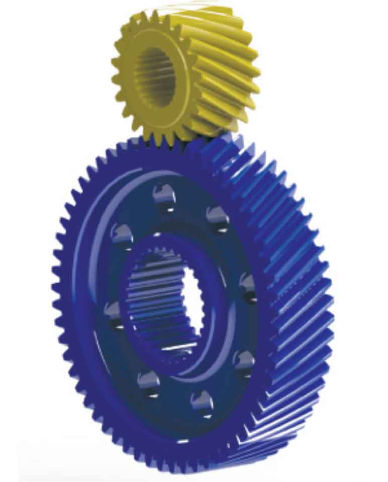
Taking the high-speed input stage gear pair in the secondary reducer of a pure electric vehicle as the research object, its basic parameters and three-dimensional model are shown in Table 1 and figure 1 respectively.
| Parameters | Driving wheel | Driven wheel |
| Number of teeth Z | 22 | 59 |
| Gear rotation direction | Dextral | Sinistral |
| Normal modulus Mn (mm) | 2 | 2 |
| Normal pressure angle α (°) | 18.5 | 18.5 |
| Helix angle β (°) | 32 | 32 |
| Tooth width b (mm) | 33 | 33 |
| Displacement coefficient X (mm) | 0.2238 | -0.5436 |
| Torque T (n · m) | 100 | 268.2 |
| Modulus of elasticity e (GPA) | 210 | 210 |
| Radial bearing stiffness KPY (n / M) | 808000000 | 398000000 |
| Axial bearing stiffness KPZ (n / M) | 685000000 | 316000000 |
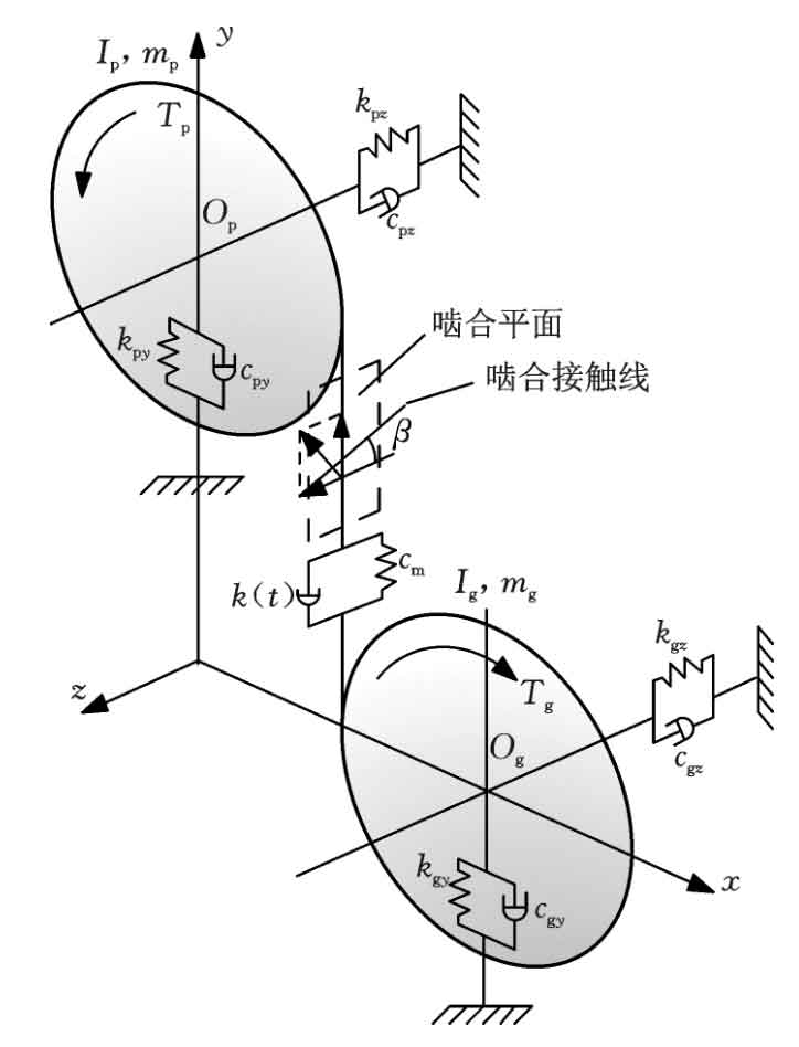
The concentrated mass method is used to establish the six degree of freedom bending torsion shaft coupling dynamic model of helical gear transmission, as shown in Figure 2. The differential equations listed according to the dynamic model shown in Figure 2 are as follows:
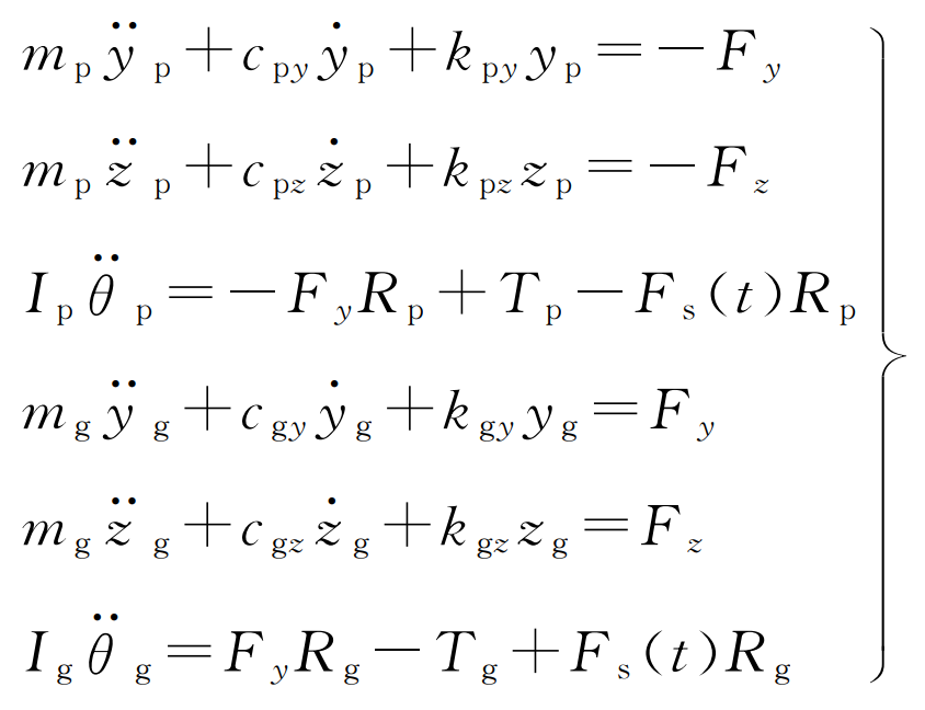
Where MP and Mg are the mass of helical gear driving and driven wheels respectively; RP and RG are the base circle radius of the main driven wheel respectively; TP and TG are the torque of main and driven wheels respectively; YP and YG are respectively the vibration displacement of the center of the main driven wheel in the Y direction; ZP and ZG are respectively the vibration displacement of the center of the main driven wheel in the Z direction; IP and Ig are the moment of inertia of the helical gear driving and driven wheels respectively; θ p、 θ G torsional displacement of the center of the main and driven wheels respectively; KPY and kGy are the equivalent support stiffness of the main and driven wheels in the Y direction respectively; KPZ and KGZ are the equivalent support stiffness of the main and driven wheels in the Z direction respectively; CPY and cGy are the equivalent support damping of helical gear driving and driven wheels in the Y direction respectively; CPZ and CGZ are the equivalent support damping of helical gear driving and driven wheels in the Z direction respectively; FS (T) is the meshing impact force.
In the model, the tangential dynamic meshing force and axial dynamic meshing force are expressed in the form of parameters as follows:
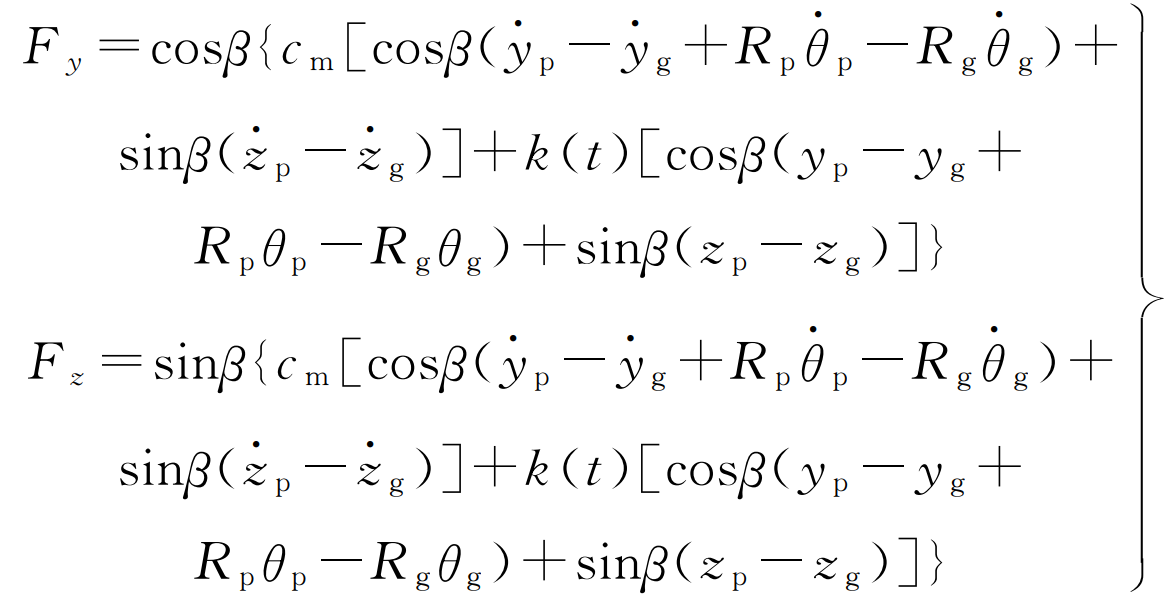
Among them, β Is the helix angle; α Is the pressure angle; K (T) time-varying meshing stiffness; Cm is the meshing damping, and its calculation formula is as follows:
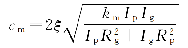
Where, ξ Is the damping ratio, taken as 0.1; Km time-varying meshing stiffness mean.
The relative angular displacement q is introduced to convert the angular displacement into linear displacement, and its expression is as follows:
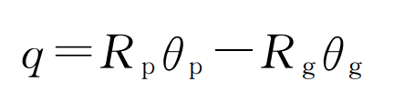
Substituting the formula, the torsional vibration equation becomes:
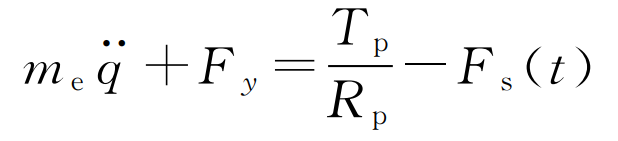
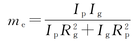
Where, me is the equivalent mass of helical gear pair, and its expression is: