
For the single-tooth model, the tooth surface is divided into the following three types according to the figure, and the heat transfer coefficient is calculated for each surface:
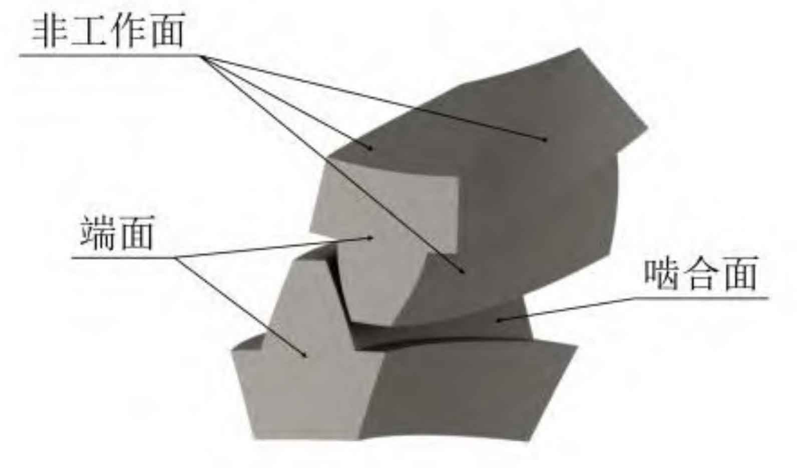
1. Engagement surface
Convective heat transfer coefficient of spiral bevel gear tooth meshing surface is generally determined by the following empirical formula:
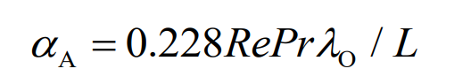
Where, Re, Pr λ O is the Reynolds number, Prandt number and thermal conductivity of the lubricating oil; L is the characteristic length, and the diameter of the indexing circle of spiral bevel gear can be taken.
2. End face
The lubricating oil at the end face of spiral bevel gear can be divided into laminar flow, transitional laminar flow and turbulent flow according to its Reynolds number.
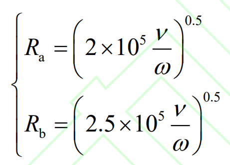
Where, Ra and Rb represent the maximum disk radius corresponding to laminar flow and the minimum disk radius corresponding to turbulent flow respectively; ν Is the kinematic viscosity of lubricating oil; ω Is the rotational angular velocity of the disk.
The end face of spiral bevel gear is simplified as a disk for analysis. By comparing the radius of any point on the disk with Ra and Rb, the flow state of lubricating oil at that position can be determined, and then the appropriate heat transfer formula is selected for calculation. The formula is as follows:
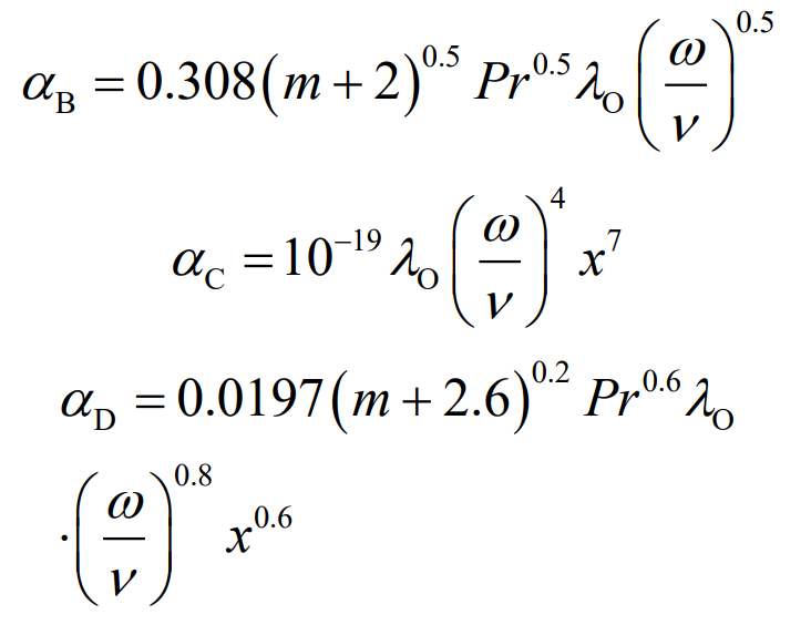
Where, subscripts B, C and D represent laminar flow, transitional laminar flow and turbulent flow; M is an exponential constant, which is used to define the radial distribution of the disk surface temperature. In this paper, the temperature is assumed to be a quadratic distribution, and m is taken as 2; X is the radius of the selected position on the disk; Others are the same as above.
3. Non-working face
The convective heat transfer coefficients of the tooth root, tooth top, non-meshing surface and tooth section can be approximately 1/3~1/2 of the mean value of the end face flow heat transfer coefficient.