
For planetary gear output type planetary gear reducer, during its operation, the planetary gear not only makes translation around the input central axis, but also makes rotation around its own geometric center.
The mechanism diagram of star gear reducer is shown in Figure 1.
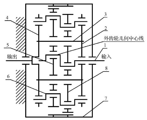
In Figure 1, when the input crankshaft 1 rotates clockwise, the left star wheel 5 and the right star wheel 8 move horizontally; at the same time, due to the meshing restriction with the fixed internal gear 8, the transmission crankshaft 6 rotates counterclockwise around the center of the reducer under the influence of the attitude change of the star wheel, thus driving the support plate 4 and the output shaft to rotate counterclockwise. In this process, the eccentric direction of the transmission crankshaft is always consistent with the input shaft.
This kind of motion characteristic of planetary gear makes it do plane compound circumferential motion around the input axis. As a result, the planetary gear periodically passes through the oil pool to ensure that the bearing and gear teeth can be well lubricated. However, the deformation of the planetary gear hub will have adverse effects on the meshing transmission between the planetary gear and the internal gear. At present, there is no theoretical calculation method for the influence degree, and most of them are based on the numerical simulation method of finite element.
Taking a certain type of star gear reducer as an example, the simplified strength calculation and the interference check of tooth tip show that the parameters meet the design requirements.