
As one of the important components of gear stiffness, it is very important to calculate the matrix stiffness reasonably and accurately. According to the domestic and foreign scholars’ summary and verification of their mathematical calculation methods by numerical or finite element method, effective mathematical evaluation models and methods have been achieved, and the mathematical calculation methods proposed in the research results are widely used.

Based on Muskhelishvili’s theory, the mathematical model is an approximate statistical method which applies the fillet / matrix flexibility analysis theory to the calculation of circular elastic ring. The reliability of the algorithm is better than that of Weber’s method, especially for multi tooth or large gear features. The geometric and physical calculation model proposed by this method is shown in Fig. 1. Considering the geometric parameters and load parameters such as the size of the shaft diameter installed in the gear body, the geometric characteristics of the regular circular gear body, and the position of the tooth load, the mathematical calculation method of the anti deformation ability of the matrix is proposed, such as the formula. The numerical calculation of L *, m *, p * and Q * is the same as the formula, and the dimensionless h is the radius of the tooth root circle and the ratio of RF to the radius of the hole RA.
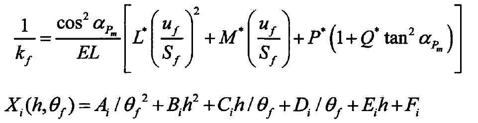
Where:
UF the distance between the root circle and the center of the action point, m;
SF arc length corresponding to single tooth root, m;
θ F – half arc angle of single tooth root, RAD;
H – dimensionless parameter, H = RF / RA
Combined with the basic parameters of the gear pair, the radius of the hole is selected to calculate the matrix stiffness of the gear pair. In Fig. 2, the matrix stiffness curves of three pairs of gear pairs under different parameters are drawn respectively. The graph shows that the driving gear shows a nonlinear decreasing trend along the meshing line, while the driven gear shows a nonlinear increasing trend. Combined with the geometric motion characteristics of the gear pair from meshing in to meshing out, the matrix stiffness shows a nonlinear decreasing trend when the applied load moves from the tooth root to the tooth top through the meshing point The effect of urbanization.

Taking gear pair 1 as an example, the matrix stiffness curves under different action apertures are studied. The simulation results are shown in Figure 3. The stiffness curve in the figure shows that the matrix stiffness of the same meshing position increases with the increase of the hole radius, and the increase of the equal aperture causes the increase of the unequal matrix stiffness, which indicates the nonlinear relationship between the hole radius and the matrix stiffness. At the same time, when the action point moves from the root to the top, the numerical increment of the matrix stiffness decreases gradually. It can be seen that the stiffness of the gear matrix can be adjusted by changing the matching aperture between the gear and the shaft, and the increase of the shaft radius can further improve the anti torsion performance and speed of the rotor, which has a significant effect on the high-speed gear pair.
