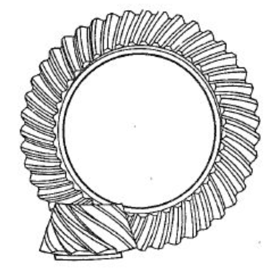
Hypoid gears are critical components in automotive drive axles, operating under high-speed and heavy-load conditions. Their meshing performance is significantly influenced by system deformation, which induces misalignment and uneven load distribution. This study proposes a novel methodology to calculate the meshing efficiency of hypoid gears while accounting for system deformation effects.
1. System Deformation and Gear Misalignment
The drive axle system, comprising shafts, bearings, and housings, undergoes deformation under load. The total misalignment between hypoid gears is calculated using stiffness equations:
$$ \mathbf{K} \cdot \delta = \mathbf{F} $$
where $\mathbf{K}$ represents the system stiffness matrix, $\delta$ denotes nodal displacements, and $\mathbf{F}$ is the external force vector. Key misalignment parameters include:
| Parameter | Symbol | Expression |
|---|---|---|
| Axial displacement | ΔP | $\Delta P_1 + \Delta P_2$ |
| Radial displacement | ΔW | $\Delta W_1 + \Delta W_2$ |
| Offset displacement | ΔY | $\Delta Y_1 + \Delta Y_2$ |
| Angular misalignment | ΔΣ | $\Delta \Sigma_1 + \Delta \Sigma_2$ |
2. Tooth Surface Generation
The actual tooth surfaces of hypoid gears are generated using machine tool parameters through coordinate transformations. For a pinion, the surface coordinates in workpiece system are derived as:
$$ \mathbf{r} = f_r(\theta_d, \phi_d, \xi_c) $$
$$ \mathbf{n} = f_n(\theta_d, \phi_d, \xi_c) $$
where $\theta_d$ and $\phi_d$ represent tool rotation angles, and $\xi_c$ contains machine setting parameters.
3. Mixed Lubrication Friction Model
The mixed lubrication friction coefficient combines boundary and fluid lubrication effects:
$$ \mu_{ML} = \mu_{FL}f_K^{1.2} + \mu_{DC}(1 – f_K) $$
where $f_K$ is the load-sharing factor calculated by:
$$ f_K = \frac{1.21\lambda^{0.64}}{1 + 0.37\lambda^{1.26}} $$
The dimensionless film thickness $\lambda$ is expressed as:
$$ \lambda = \frac{h_0}{\sqrt{S_{r1}^2 + S_{r2}^2}} $$
Central film thickness $h_0$ is determined by:
$$ h_0 = 2.69W^{-0.067}U^{0.67}G^{0.53}(1 – 0.61e^{-0.73k}) $$
4. Loaded Tooth Contact Analysis
The FLTCA method solves deformation compatibility and load equilibrium equations:
$$ \|\delta_b + \delta_s + \delta_c – (Z – d_0)\| < \epsilon_1 $$
$$ \sum_{i=1}^m \sum_{j=1}^n (F_{f_{ij}} + F_{N_{ij}}}) \mathbf{r}_{ij} \cdot \mathbf{p} – T_{load} < \epsilon_2 $$
Key parameters for hypoid gear pairs in experimental validation:
| Parameter | Pinion | Gear |
|---|---|---|
| Number of teeth | 10 | 39 |
| Module (mm) | 7.7 | 7.69 |
| Pressure angle (°) | 22.5 | 22.5 |
| Spiral angle (°) | 44.0 | 30.8 |
5. Meshing Efficiency Calculation
The instantaneous power loss and meshing efficiency are calculated as:
$$ \eta_{g,fric} = \frac{|T_{out}|\omega_{out}}{|T_{out}|\omega_{out} + p_{g,fric}} $$
$$ p_{inst} = \sum_{i=1}^m \sum_{j=1}^n F_{f_{ij}}}V_{s_{ij}} $$
Experimental results demonstrate:
| Condition | Speed (km/h) | Efficiency (%) |
|---|---|---|
| 80 kW load | 10 | 97.2 |
| 80 kW load | 80 | 98.3 |
| 1354 N·m torque | 60 | 97.8 |
6. Conclusion
This methodology enables accurate prediction of hypoid gear meshing efficiency under actual operating conditions. System deformation causes measurable shifts in contact patterns (up to 545 μm offset at full load) and reduces efficiency by 1.1–1.5% in heavy-load scenarios. The proposed approach provides critical insights for optimizing hypoid gear designs in automotive drive axles.
