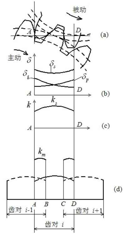
Taking straight teeth as an example, the basic concept and properties of gear meshing stiffness are explained. Tooth meshing stiffness refers to the comprehensive effect of tooth pairs participating in gear meshing in the gear meshing area (segments A-D in Figure 1), which is mainly related to the elastic deformation of a single tooth, the comprehensive elastic deformation of a single pair of teeth participating in gear meshing and the coincidence degree of gear.
Single tooth deformation refers to the elastic deformation of a single tooth under the action of external load, including bending deformation, contact deformation and shear deformation. In Figure 1 (b) δ P and δ G represents the deformation curves of single driving and driven teeth in the gear meshing area during the gear meshing process. It can be seen from the figure that at the beginning of gear meshing (point a), the driving gear is meshed at the tooth root, and the elastic deformation is small; The driven gear meshes at the tooth top and has large elastic deformation; When the gear mesh is terminated (point d), the situation is the opposite.
The comprehensive elastic deformation of a single pair of teeth refers to the sum of the elastic deformation of a pair of teeth meshed with each other during the whole gear meshing process, and its expression is:
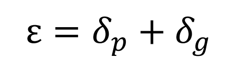
Since the driving gear and the driven gear mesh with each other at the tooth top and the tooth root and the tooth top respectively, the superimposed tooth elastic deformation curve is shown in Figure 1 (b) δ s。
The comprehensive stiffness KS of a single pair of teeth is shown in Figure 1 (c), expressed as:
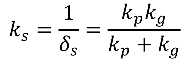
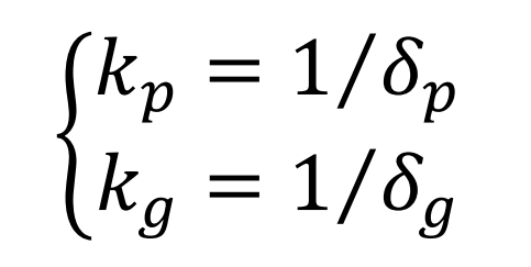
Where KP and kg are the single tooth stiffness of main and driven gears respectively, i.e.:
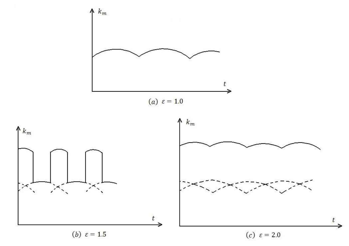
For the gear meshing stiffness, as shown in Figure 1 (d), in the double tooth pair gear meshing area, two pairs of teeth participate in meshing at the same time. At this time, the stiffness curve is formed by the superposition of the meshing stiffness of two pairs of teeth. It can be seen from the figure that the meshing stiffness of the gear has obvious step and sudden change in the meshing process. When the coincidence degree of the gear is different, the meshing stiffness curve of the gear will have different forms. Figure 2 shows the coincidence degree ε Tooth meshing stiffness curves at 1.0, 1.5 and 2 respectively. It can be seen from the figure that when the gear coincidence degree is an integer, the change of gear meshing stiffness is small, and there is no step mutation.