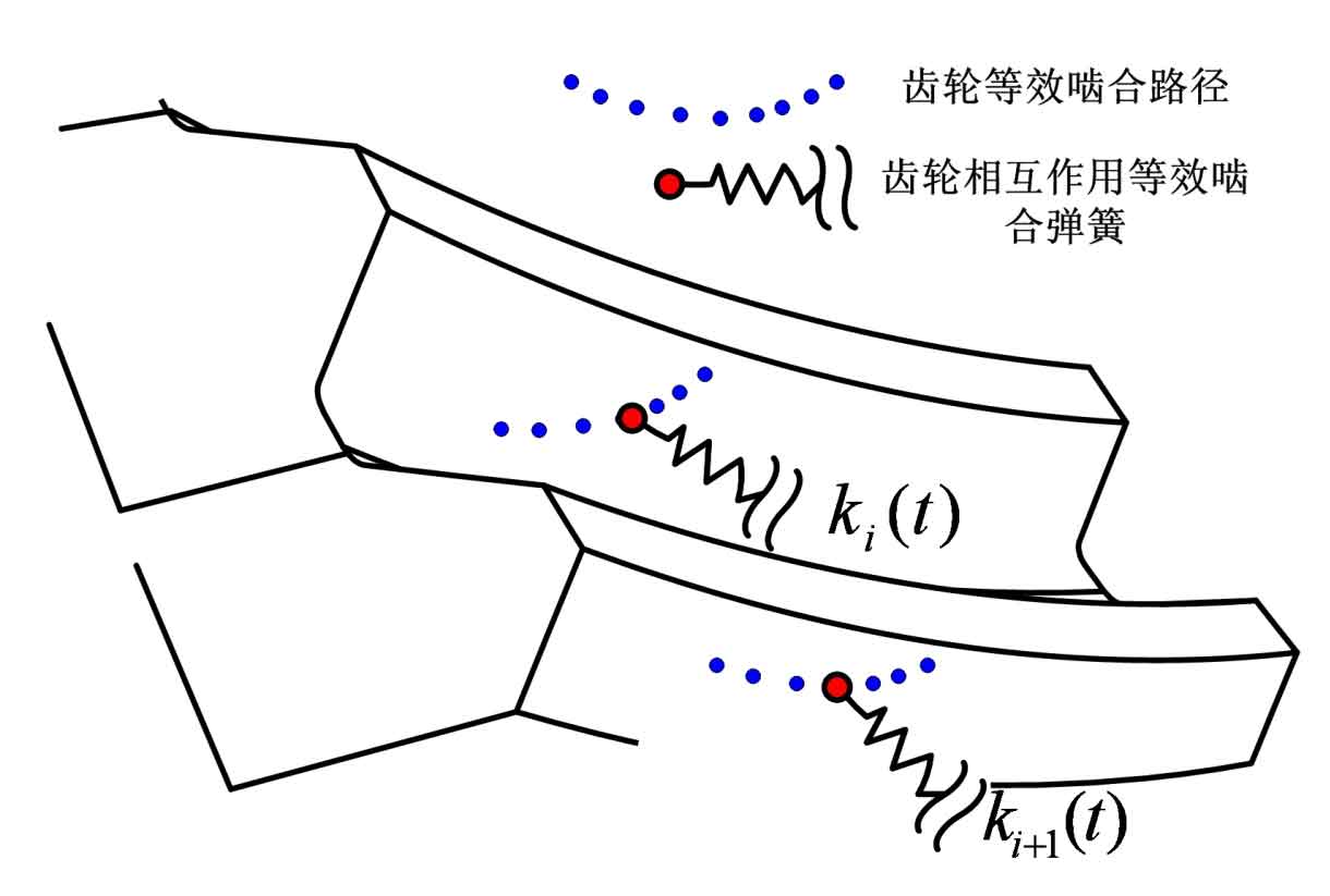
Fig. 1 shows the meshing coupling model of hypoid gear based on the finite element model. From the meshing diagram, it can be seen that at any meshing moment, there are multiple contact areas between the large and small wheels of the hypoid gear, and the number of interaction contact areas is related to the load and the rotation position of the hypoid gear. The relationship between the action points can be determined by the equivalent meshing stiffness and meshing deformation. Each interaction point includes the influence of tooth side clearance and friction nonlinear factors. The model does not need more assumptions and constraints, so it can more accurately simulate the contact of hypoid gears and more accurately calculate the meshing stiffness of hypoid gears.
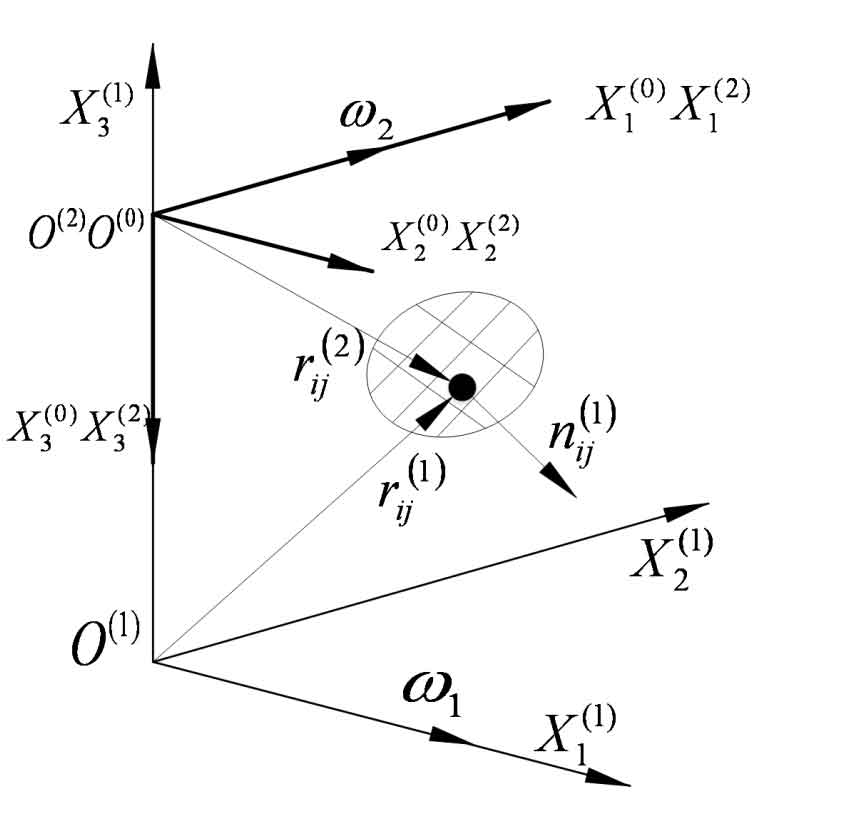
When the space shape of the hypoid gear is fixed, the direction of the meshing force in the meshing process is related to the meshing position and the loading force of the hypoid gear. Therefore, the meshing stiffness of the hypoid gear must be determined according to the meshing position and the loading force of the hypoid gear. The coordinate system as shown in Fig. 2 is established. The coordinate systems S1 and S2 are fixedly connected to the hypoid gear small wheel and the hypoid gear large wheel respectively. S0 is the global coordinate system coincides with the coordinate system S2. The coordinate origin of the coordinate system S1 is located at the intersection of the axis of the hypoid gear pinion and the axis of the large gear. The X (1) 1 axis coincides with the axis of the pinion, and points from the small end of the pinion to the large end. The X (1) 2 axis is parallel to the axis of the large gear, and also points from the small end of the large gear to the large end. The X (1) 3 axis is determined by the right-hand rule. The large gear coordinate system S2 is defined in the same way.