
Same as spur gear. In the actual working state of the central bevel gear, the meshing of the teeth is also an alternating process. At different times, the meshing position between the teeth and the number of teeth involved in meshing will change alternately with the rotation of the bevel gear. Therefore, the comprehensive meshing stiffness between the bevel gears changes periodically, which is called time-varying comprehensive meshing stiffness.
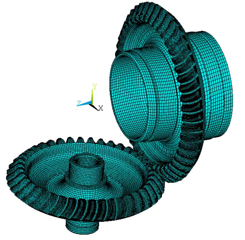
The finite element model of the central bevel gear in the meshing state is shown in Figure 1. Considering the complexity of the spiral bevel gear structure, ANSYS software is used to calculate its time-varying meshing stiffness in the meshing process. In finite element analysis, whether the boundary conditions of the model are correct or not and whether the external load is handled properly will have a great impact on the calculation results. At first, when the meshing stiffness is calculated by finite element method, the meshing force of bevel gear is generally applied to the meshing point of bevel gear as a concentrated force. The tooth deformation calculated in this way is actually the deformation under the action of concentrated force. In fact, in the process of tooth meshing, the teeth are actually a contact area, and the meshing force of bevel gear is actually a distributed force rather than a concentrated force. Therefore, the method of treating the meshing force of bevel gear into concentrated force will produce large errors.
When calculating the deformation of spiral bevel gear in this paper, the contact element in the finite element calculation software ANSYS will be used to simulate the actual meshing state of gear teeth. In order to simulate the actual working state of the spiral bevel gear, the boundary condition for calculating the natural frequency of the spiral bevel gear is adopted, and the contact element is established between the tooth surfaces of the spiral bevel gear. Different from the constraint boundary of vibration calculation, the node on the connecting surface a between the driven bevel gear and the central transmission rod is constrained to the degrees of freedom in all directions. Apply a torque value to the contact surface between the driving bevel gear and the transmission shaft. Under the action of this torque, a circumferential torsional deformation angle will be generated at the meshing place between the driving bevel gear and the driven bevel gear Δθ z , Δθ c 。 Then, the comprehensive meshing torsional stiffness K of driving bevel gear and driven bevel gear under this meshing state is calculated θ Z and K θ c。 Then rotate the driving bevel gear by a small angle to obtain the comprehensive meshing torsional stiffness of the central bevel gear pair in the next meshing state. Repeat the above steps to obtain the single tooth meshing torsional stiffness of the central bevel gear in the meshing state. It needs to be converted into the comprehensive torsional stiffness of the central bevel gear pair through the formula.

Where:
K θ — Comprehensive meshing torsional stiffness of bevel gear;
K θ Z – Comprehensive meshing torsional stiffness of driving bevel gear;
K θ C – Comprehensive meshing torsional stiffness of driven bevel gear.
The stiffness value calculated by the formula is the comprehensive meshing torsional stiffness value of the central bevel gear, which needs to be converted into the comprehensive meshing stiffness value by the formula.

Where:
RV – equivalent radius of meshing bevel gear;
RZ – radius value of driving bevel gear root circle;
RC – radius value of driven bevel gear root circle.
The comprehensive meshing stiffness of the central bevel gear of an aeroengine is obtained by finite element calculation.
The calculated discrete stiffness value is Fourier transformed through the formula to obtain the curve expression of discrete stiffness.
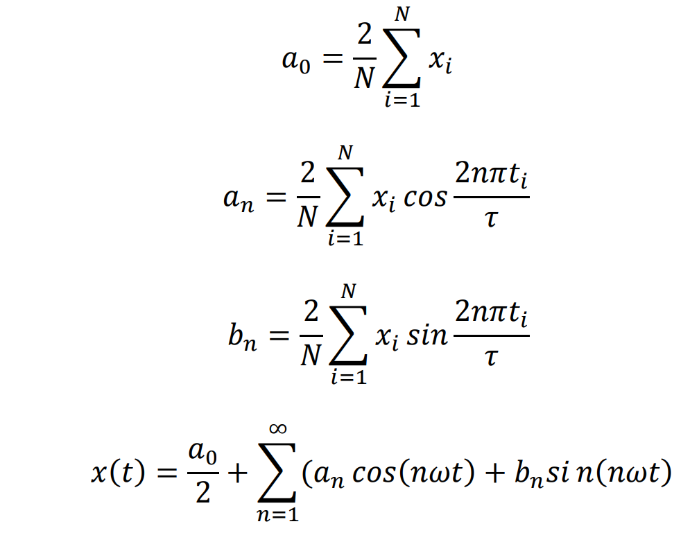
In order to obtain the comprehensive expression of the meshing stiffness of the bevel gear by assuming that only the change of the center cosine of the Fourier transform can be used as the reference for the comprehensive analysis of the meshing stiffness of the bevel gear:

The comprehensive meshing stiffness curve of central bevel gear is shown in Figure 2:
