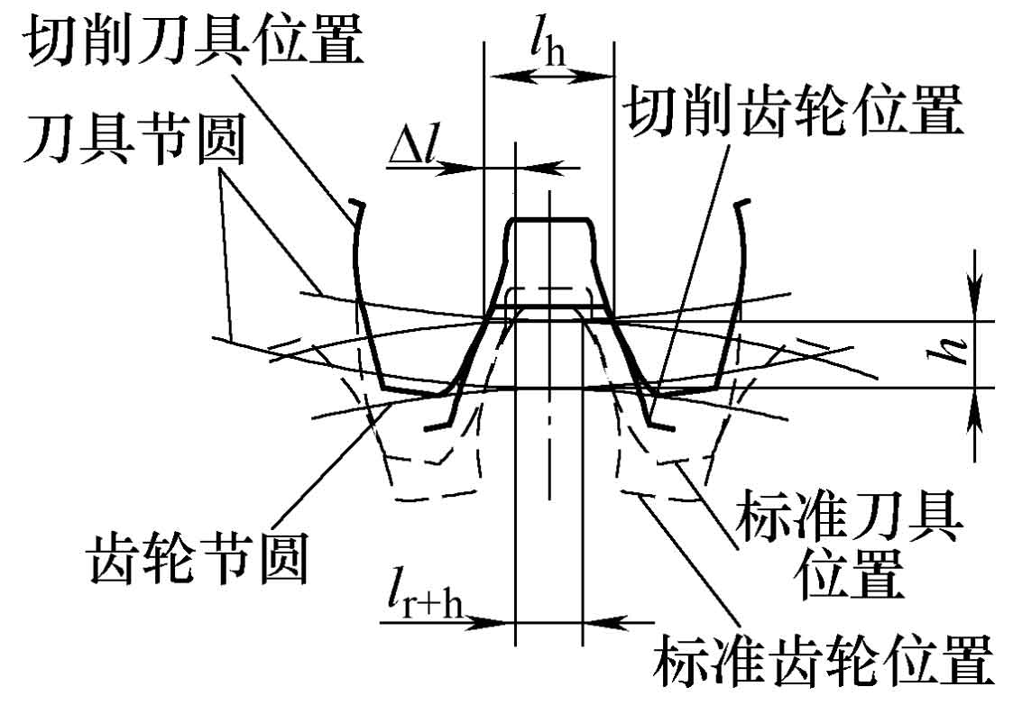
In essence, the machining of gear is that the tool continuously feeds along the radial direction of the gear, and then develops into a circular motion to cut the tooth shape. As shown in the figure, the dotted line indicates that the theoretical standard gear is obtained when the cutting depth of the tool reaches the standard position. When the tool has not been cut to the standard position, that is, when the tool in the figure is far away from the standard position h, the cut tooth shape is the solid line part in the figure, which can be known from the cutting process, The position of the gear blank does not change, while the tool does the cutting motion of synchronous meshing with the gear when it is fed to different cutting depth positions. Because the parameters of the tool are fixed, the involute of the meshing part with the tool is unchanged. It can be concluded that when it is fed to the H position in the figure, the tooth slot width on the tool pitch is equal to the arc tooth thickness of the tooth part to be cut, and the meshing line is the equidistant curve of the standard meshing line at h.
At h, the tooth groove width on the tool pitch circle L = π M / 2, then the arc tooth thickness LH of the gear blank at H:
The spiral tooth thickness Lr + H of the standard gear at h can be obtained from the formula:
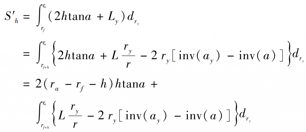
The tooth area s ′ h at the cut gear h can be obtained from the formula:
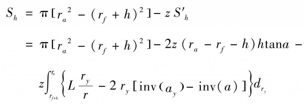
The total area of the gear to be cut removed at h can be obtained from the formula:


