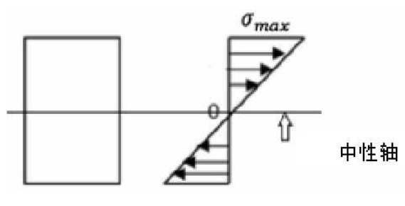
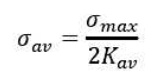
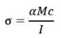
Since the gear tooth is simplified as a cantilever beam with variable cross-section, the stress distribution of the gear tooth cross-section is shown in Fig. It can be seen from the figure that the bending stress of the gear tooth along the neutral axis of the section to the top or bottom of the tooth section changes linearly. Therefore, the average bending stress from the neutral axis to the top or bottom of the tooth section will be half of the maximum bending stress at the top or bottom of the tooth section. The total average bending stress σ AV along the tooth height direction can be expressed as the maximum bending stress σ max at the tooth root
The relationship between strain and stress is introduced into the following equation
According to Hooke’s law σ = e ε, the formula can be expressed as follows:
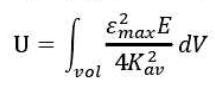
In the formula, ε Max is the maximum bending strain of tooth root. The relationship between the bending strain of tooth root and the strain energy of gear tooth is established. Therefore, the elastic strain energy stored in gear tooth can be obtained by calculating the bending strain of tooth root measured by strain sensor in the experiment.
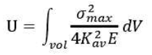
According to the energy method, the meshing stiffness of gears is calculated. The energy in the teeth is calculated by using the formula, and the meshing stiffness of gears can be calculated
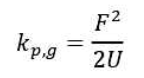
In the formula: is the normal force along the tooth profile of the meshing line gear. The relationship between the tooth root bending strain and the gear meshing stiffness is established by the above formula. Therefore, the meshing stiffness of the gear can be obtained by calculating the tooth root bending strain measured experimentally.
The formula is the stiffness calculation process of the healthy gear. When the pitting fault occurs on the tooth surface, there will be discontinuity in the meshing contact process of the gear. Due to the discontinuous and discontinuous contact of the tooth surface at the position where pitting occurs, the driving and driven gear teeth will no longer transfer the force directly near the position, which will cause the loss of torque. When pitting occurs, the formula can be modified as follows:
In the formula: α is the torque loss factor, where α can be expressed as the ratio of the length of the actual meshing line to the tooth width.
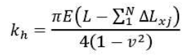
For the gear with pitting fault, the contact width of tooth surface is l − {LX instead of L, where} LX is the reduced contact width caused by pitting. Therefore, the Hertz contact stiffness of the gear pair with circular pitting can be expressed as follows: