
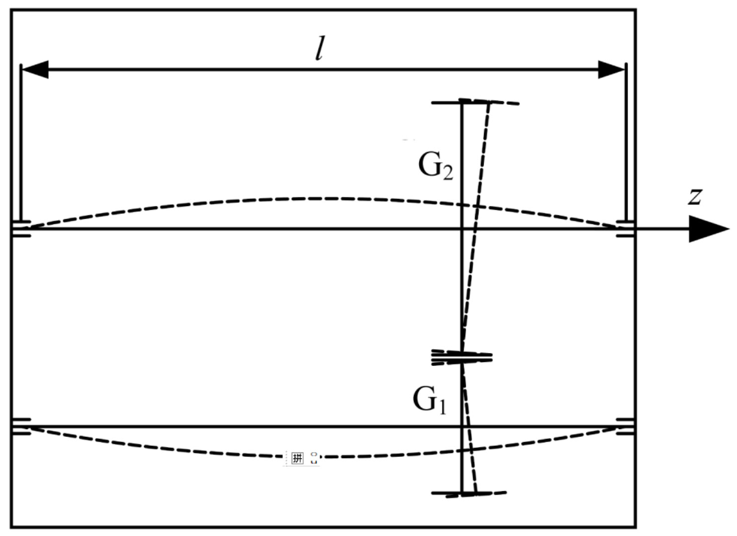
The misalignment of helical gear meshing is a key factor affecting the stability and lifespan of the helical gear pair transmission system. Select the first gear helical gear pair system of a seven speed dual clutch automatic transmission as the research object. The gear meshing misalignment caused by the deformation of the helical gear shaft is shown in the figure. In the figure, G1 and G2 respectively represent the driving and driven gears; L is the support span; The z-direction is the direction of the centerline of the helical gear.
The meshing misalignment of helical gears is divided into parallel meshing misalignment, angle deviation Mi parallel to the meshing plane, and angle deviation Mj perpendicular to the meshing plane. The change in overlap caused by parallel meshing misalignment is relatively small, and there is no significant change in the contact area of the tooth surface caused by Mj, so it can be ignored.
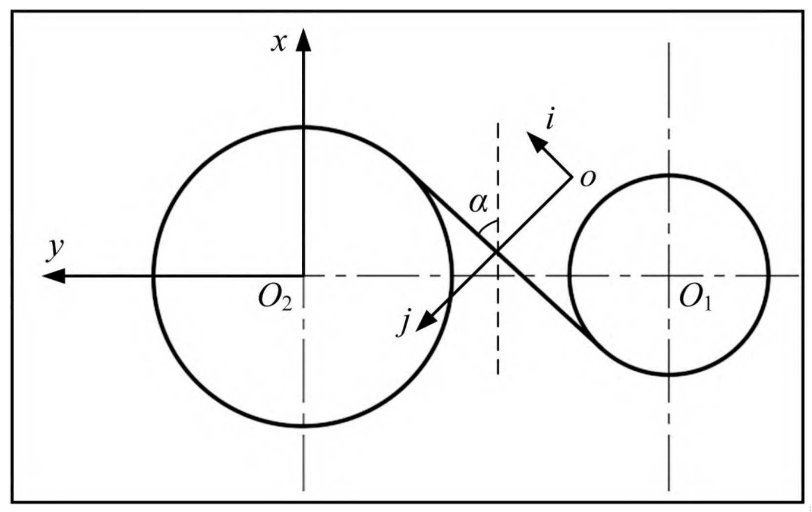
Mi reduces the contact area of the tooth surface and causes serious meshing misalignment of the helical gear. The coordinates of the helical gear meshing line are shown in Figure 2, where o-ij represents the helical gear meshing plane. So Mi is:
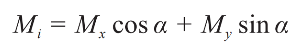
In the equation: α Is the normal pressure angle; Mx is the angular deviation of the meshing plane from the vertical plane of the centerline of the two helical gears, Mx=tan θ x; My is the angular deviation of the meshing plane relative to the plane where the centerline of the two helical gears is located, My=tan θ y; θ x、 θ Y represents the angle between the radial force on the four bearings and the positive direction of the x and y axes.
Taking into account the influence of the deformation fshn (n=1,2) of the main and driven gear shaft systems, bearing displacement fbe, and elastic deformation fca of components such as the box on the meshing misalignment of helical gears.
The meshing misalignment of helical gears caused by deformation of the main and driven gear shaft systems can be expressed as:
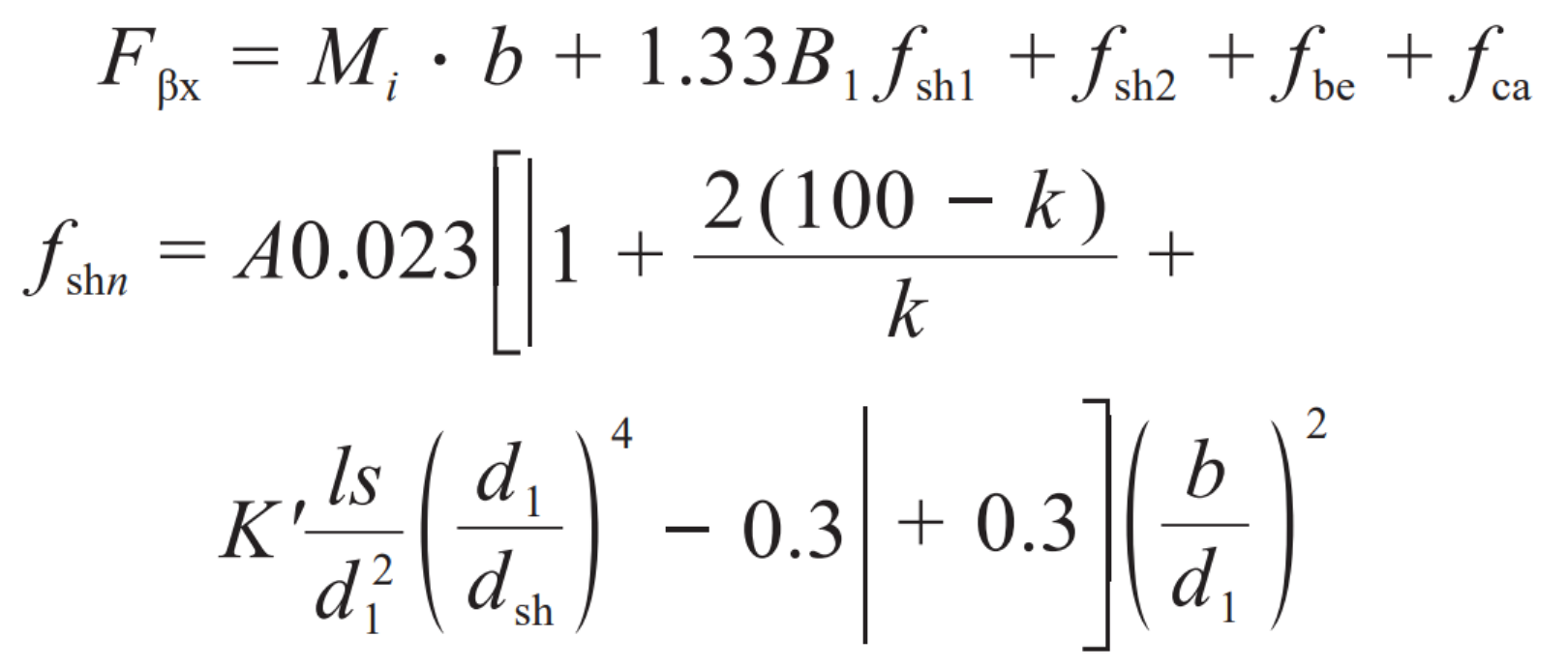
In the formula: F β X is the misalignment of helical gear meshing; B is the tooth width; B1 is the coefficient of the equation, B1=0.5~1; Fsh1 and fsh2 are the deformations of the main and driven gear shaft systems caused by the deformation of the helical gear and shaft, respectively; A is the average load per unit tooth width; K is the percentage of input power to total power, and when the total power is transmitted through a single mesh, k=0.8; S is the distance between the helical gear and the bearing support center position; D1 is the outer diameter of the helical gear shaft; Dsh is the inner diameter of the helical gear shaft; K ‘is the position relationship constant of the driving helical gear relative to the torque input end. When d1/dsh ≥ 1.15 and s/l<0.3, K’=-0.48.
FBE and FCA can be solved using the finite element method.