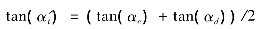
The helical gear is divided into m slice helical gears along the tooth width direction AA ‘, the M slice helical gear is equivalent to m slice spur gear, and the meshing position parameter value takes the average value of the meshing position parameter values of the two meshing points. As shown in Figure 1, when the meshing line is BC, take the slice helical gear where a section of Cd on the meshing line BC is located, equivalent it to a slice spur gear, and note that the meshing position parameter of the slice spur gear is tan( α’ t ):
The tooth width is taken as the distance between the meshing points c and D. According to the formula, the meshing position parameters and tooth width of each sheet spur gear involved in meshing can be obtained. Then, according to the theory of material mechanics, considering the bending deformation, shear deformation, radial compression deformation, Hertz contact deformation and wheel body deformation of the gear, the equivalent stiffness of each sheet spur gear pair along the meshing line at this rotating position can be obtained. The equivalent stiffness of each slice spur gear is added to obtain the meshing stiffness of the helical gear at this rotation position.

The traditional method of material mechanics is used to calculate the meshing stiffness of helical gears, and the influence of axial deformation caused by axial force is not considered. Based on the stress and deformation decomposition of helical gear, the relationship between the normal deformation of helical gear and the meshing direction deformation of helical gear end face is analyzed, and the meshing stiffness of modified helical gear is obtained. The stress and deformation decomposition of helical gear is shown in Figure 2.
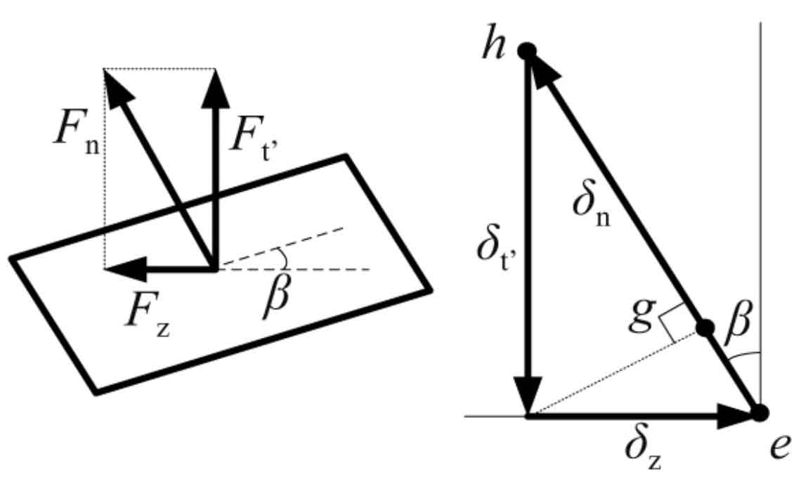
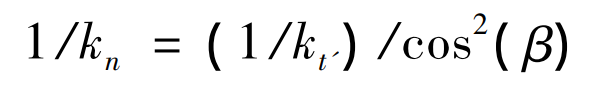
In Fig. 2, FN represents the normal load on the helical gear, and the force FN is decomposed into the component force FZ along the axial direction and the component force FT ‘along the meshing line of the end face, δ N represents normal deformation, δ Z and δ T ‘represents normal deformation δ N decomposition along the axial direction and the meshing line of the end face. According to the traditional calculation method, if only one slice helical gear is equivalent to a slice spur gear, when calculating its stiffness, only the influence of end face meshing force FT ‘is considered, and the influence of axial force FZ is not considered. Assuming that the stiffness obtained by considering only the influence of the end face meshing force FT ‘is KT’, FN / KT ‘represents the deformation of the helical gear along the end face meshing direction δ T ‘is equivalent to the deformation in the normal direction, as shown in the GH segment in Figure 2. According to the geometric relationship in Fig. 2, the meshing stiffness kN of helical gear considering the influence of axial deformation can be obtained, and the expression is: