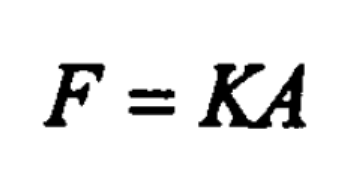
Several common formulas for calculating the precision forging forming force of spur bevel gears are given below.
Formula 1:

Where
F – total deformation area (including spur bevel gear forgings, skin and flash), unit: mm2;
K – steel grade coefficient (k=0.9 for carbon structural steel with carbon content lower than 0.25%; k=1 for carbon structural steel with carbon content higher than 0.25% and low alloy steel with carbon content lower than 0.25%; k=1.1 for low alloy structural steel with carbon content higher than 0.25% and k=1.25 for high alloy structural steel).
Formula 2:

Where
V – volume of straight bevel gear forging and flash, unit: mm3;
A – projection area of straight bevel gear forging and flash in horizontal direction, unit: mm2;
σ B – tensile strength of material at deformation temperature, unit: MPa, table 1 gives the tensile strength at different deformation temperatures;
K – coefficient (k=4 when the teeth are full of fins and the outer diameter of the fins is 2-4mm larger than the outer diameter of the straight bevel gear forging; k=3 when the fins are distributed along the tooth shape and the width is <1.5-2mm.
| Deformation temperature ℃ | 800 | 900 | 1000 | 1100 | 1200 |
| Tensile strength Mpa | 147 | 97 | 80 | 44 | 28 |
Formula 3: CheY formula (American Iron and Steel Institute)

Where
C1 – coefficient, which is related to the complexity of spur bevel gear forgings. For the case that the die forging of spur bevel gear forgings with complex shape has flash, take 8-12;
A – projected area of spur bevel gear forging on the parting surface (including the flash bridge), unit: mm2;
σα — The average flow stress of metal under average forging temperature and average strain rate. If the deformation resistance of metal is only related to strain, the average flow stress under average strain shall be taken, in MPa.
Formula 4:

Where
Y – yield strength of material at forging temperature, unit: MPa;
A – Horizontal projected area of spur bevel gear forgings (including flash bridge), unit: mm2.
Formula 5: experience recommended data
| Nominal pressure of friction press /kN | 3000 | 4000 | 10000 |
| Maximum weight of precision forged gear /kg | 1 | 1.5 | 7 |
Formula 6:

Where
A – Horizontal projected area of straight bevel gear forgings, unit: mm2;
K – coefficient, 80kn/cm2 for straight bevel gear forgings with clear profile, 50kn/cm2 for straight bevel gear forgings with certain rounded corners, and 120-150kn/cm2 for straight bevel gear forgings with high rib and thin wall at 1200 ℃.
The precision forging force of spur bevel gear calculated by the above formula is listed in Table 3
| Workpiece | Forming force | Formula 1 | Formula 2 | Formula 3 | Formula 4 | Formula 5 | Formula 6 |
| Planet gear | Pre forging | 4575 | 5563 | 4421 | 3179 | 3000 | 4046 |
| Planet gear | forging | 4455 | 6058 | 5201 | 4507 | 3000 | 4623 |
| Halfshaft gear | Pre forging | 13691 | 13681 | 11195 | 8049 | 10000 | 10244 |
| Halfshaft gear | forging | 13744 | 14883 | 13171 | 11415 | 10000 | 11707 |
