
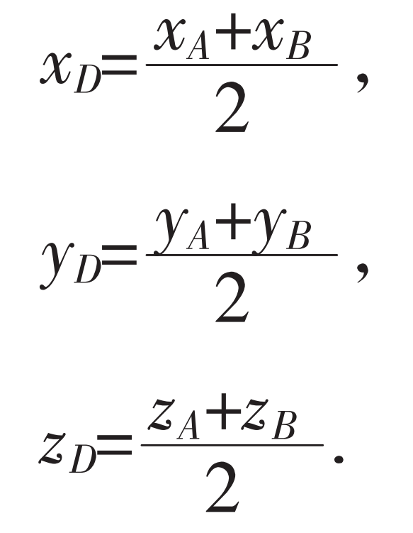
In order to predict the surface topography generated in each simulation area, the local coordinate system OWXWYWZW attached to the workpiece (spiral bevel gear tooth surface) is defined. The definition of the local coordinate system of each simulation area is based on the position of the tool point and the cutter axis direction of the reference milling path given in the machining program. The origin OW and axis ZW are the first system elements. To achieve this, consider a set of auxiliary elements (a point M and two unit vectors ^ u and ^ q). First, select two interpolation points A and B at the center of the reference track, and consider the midpoint D of linear interpolation between point A and point B. The coordinates of point D (xD, yD, zD) are functions of the coordinates of point A and point B (xA, yA, zA) and (xB, yB, zB):
Considering the tool axis direction, when the tooltip is from point A to point B, the position of the tool center point can be calculated by equation when the tooltip point is at point D.
The roughness model is developed for the geometric shape of ball-end milling cutter. Its behavior is similar to that of a conical cutter, and it only cuts the tooth finish path in the spherical area of the tool tip. Figure 1 shows the three-dimensional geometry of ball-end milling cutter with radius R and helix angle i0. Only one edge is shown in the figure (Figure 2), but the developed model is a generalization of Nt edging machine. Suppose that the cutting edge shown in the figure represents an edge of the milling cutter, called k edge, where k=1, 2,…, Nt. In order to define the position of the point on the k side, define a reference system OTXTYTZT connected to the ball-end milling cutter.
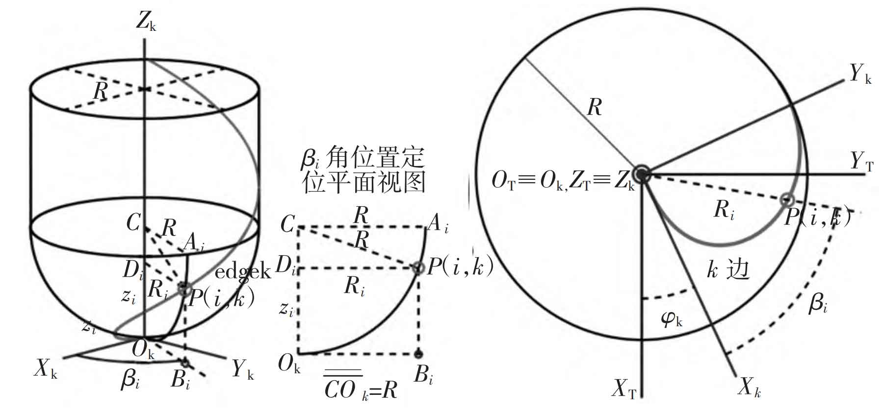
The reference system origin OT is located on the tool tip coincident with the tool axis. The ZT axis corresponds to the tool axis XT, which is radially tangent to the projection of side 1 on the plane containing point OT and perpendicular to the ZT axis. The y-axis is perpendicular to the x-axis and y-axis, forming a right-handed system.
In order to analyze the surface roughness, the influence of tool path on each milling path is removed for each predicted profile along the YW axis. Therefore, the roughness profile is obtained. The shape of the spiral bevel gear surface is also removed from the predicted profile to obtain a black roughness profile. It can be observed that the span between milling passes has a significant impact on the terrain and roughness peak-to-valley values. However, in this case, the influence of tool feed on roughness is small.