
In this article, I will delve into the intricate calculation of surface endurance stress for hypoid gears, a critical aspect in gear design and reliability. Hypoid gears are widely used in automotive and industrial applications due to their ability to transmit power between non-intersecting shafts with high efficiency and smooth operation. The unique geometry of hypoid gears, characterized by crossed axes and curved teeth, leads to complex contact conditions that necessitate rigorous stress analysis. Specifically, I will focus on two primary methods for evaluating the contact strength of hypoid gear teeth: one based on Hertz’s theory of point contact and the other on line contact. These approaches are essential for ensuring the durability and performance of hypoid gears under various loading conditions. Throughout this discussion, I will emphasize the importance of accurately modeling the contact mechanics to prevent failures such as pitting and spalling, which are common in hypoid gear systems. By exploring these methods in detail, I aim to provide a comprehensive guide for engineers and designers working with hypoid gears.
To begin, let me introduce the fundamental concepts behind contact stress analysis. When two surfaces come into contact under load, they deform elastically, creating a contact area that can be approximated as either a point or a line, depending on the geometry. For hypoid gears, the teeth engage in a manner that initially resembles point contact due to the crossed axes, but under load, it may transition to a more extended area. Hertz’s elastic theory forms the basis for calculating the stresses in such contacts. I will first review the general equations for arbitrary surfaces in contact, then apply them to hypoid gears through a series of transformations. This will involve converting the hypoid gear pair into equivalent helical and spur gear models, which simplify the analysis while retaining the essential physics. The goal is to derive practical formulas that can be used in design calculations for hypoid gears, incorporating factors such as load distribution, material properties, and geometric parameters.
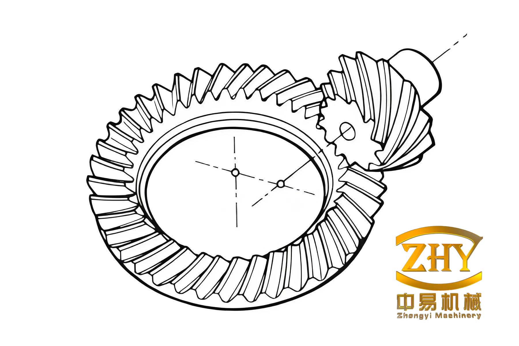
Now, let’s consider the general case of two arbitrary surfaces in contact. According to Hertz’s theory, when two bodies with curved surfaces touch at a point, the contact area under a normal load \( F_n \) becomes an ellipse with semi-axes \( a \) and \( b \). The principal curvatures at the contact point define the geometry. For surfaces \( K_1 \) and \( K_2 \), let \( k_{11} \) and \( k_{12} \) be the minimum and maximum principal curvatures for \( K_1 \), and \( k_{21} \) and \( k_{22} \) for \( K_2 \). The angle between the principal planes of the two surfaces is denoted by \( \varphi \). The semi-axes of the contact ellipse are given by:
$$ a = m_a \sqrt[3]{\frac{3 F_n}{4 C} \cdot \frac{1 – \nu_1^2}{E_1} + \frac{1 – \nu_2^2}{E_2}} $$
$$ b = m_b \sqrt[3]{\frac{3 F_n}{4 C} \cdot \frac{1 – \nu_1^2}{E_1} + \frac{1 – \nu_2^2}{E_2}} $$
Here, \( E_1 \) and \( E_2 \) are the elastic moduli, \( \nu_1 \) and \( \nu_2 \) are Poisson’s ratios, and \( C \) and \( D \) are coefficients derived from the principal curvatures:
$$ C = 0.5 (k_{11} + k_{12} + k_{21} + k_{22}) $$
$$ D = 0.5 \sqrt{(k_{11} – k_{12})^2 + (k_{21} – k_{22})^2 + 2(k_{11} – k_{12})(k_{21} – k_{22}) \cos 2\varphi} $$
The coefficients \( m_a \) and \( m_b \) depend on the ratio \( D/C \) and can be obtained from tables. For hypoid gears, this point contact model is relevant because the teeth initially meet at a point, but as we will see, the running-in process may alter the contact pattern. The maximum contact pressure \( p_{\text{max}} \) at the center of the ellipse is:
$$ p_{\text{max}} = \frac{3 F_n}{2 \pi a b} $$
In the case of line contact, such as between two cylinders, the contact area becomes a rectangle with half-width \( b \). For cylinders with principal curvatures \( k_{11} = k_{21} = 0 \) (since they are cylindrical) and \( k_{12} = 1/\rho_{12} \), \( k_{22} = 1/\rho_{22} \), where \( \rho_{12} \) and \( \rho_{22} \) are the principal radii of curvature, the half-width and maximum pressure are:
$$ b = \sqrt{\frac{4 F_n}{\pi l} \cdot \frac{1 – \nu_1^2}{E_1} + \frac{1 – \nu_2^2}{E_2}} \cdot \sqrt{\frac{\rho_{12} \rho_{22}}{\rho_{12} + \rho_{22}}} $$
$$ p_{\text{max}} = \frac{2 F_n}{\pi b l} $$
where \( l \) is the length of the contact line. These foundational equations will be adapted for hypoid gears by considering their specific geometry.
Moving to hypoid gears, the calculation of surface endurance stress requires transforming the gear pair into equivalent models. This is necessary because the hypoid gear teeth have complex curvatures and non-parallel axes. The first step is to convert the hypoid gear to an equivalent helical gear pair at the mean point of the tooth width. Let’s denote the pinion as gear 1 and the gear as gear 2. At the mean point \( P \), the normal to the pitch cones intersects the axes at points \( A_1 \) and \( A_2 \). The equivalent helical gear has parameters such as crossed-axis angle \( \Sigma_s = \beta_{m1} – \beta_{m2} \), normal module \( m_{sn} = m_n \), face width \( b_s = b \), pressure angle \( \alpha_{sn} = \alpha_n \), and helix angles \( \beta_{s1} = \beta_{m1} \), \( \beta_{s2} = \beta_{m2} \). Here, \( \beta_{m1} \) and \( \beta_{m2} \) are the spiral angles at the mean point, and \( \alpha_n \) is the normal pressure angle. The base helix angle \( \beta_{bs} \) can be calculated as \( \beta_{bs} = \arcsin(\sin \beta_{ms} \cos \alpha_n) \), and the pitch diameter \( d_{s} = d_m / \cos \delta \), where \( \delta \) is the pitch cone angle. This equivalent helical gear captures the essential kinematics of the hypoid gear pair.
Next, I transform the equivalent helical gear into an equivalent spur gear. This is done by adjusting the helix angle to an equivalent value \( \beta_e \) that preserves the normal plane parameters and center distance. The equivalent spur gear parameters are: normal module \( m_{en} = m_{sn} = m_n \), pressure angle \( \alpha_{en} = \alpha_{sn} = \alpha_n \), center distance \( a_e = \frac{1}{2}(d_{s1} + d_{s2}) \), and normal pitch diameters \( d_{en1} = d_{s1} / \cos^2 \beta_{e} \), \( d_{en2} = d_{s2} / \cos^2 \beta_{e} \). The equivalent helix angle \( \beta_e \) is derived from:
$$ \cos \beta_e = \sqrt{\frac{d_{s1} / \cos^2 \beta_{s1} + d_{s2} / \cos^2 \beta_{s2}}{2 a_e}} $$
This ensures that the normal plane geometry remains consistent. The equivalent spur gear then has parameters like pitch diameter \( d_{e} = d_{en} \cdot \cos \beta_e / \cos \beta_{bs} \), helix angle \( \beta_{e} = \arcsin(\sin \beta_e / \cos \alpha_{en}) \), transverse pressure angle \( \alpha_{et} = \arccos(\tan \beta_e / \tan \beta_{bs}) \), and transverse tooth numbers \( z_{et} = d_{e} \cdot \cos \beta_e / m_{en} \). The gear ratio is \( u_e = z_{et2} / z_{et1} \). This transformation simplifies the contact analysis for hypoid gears by reducing it to a spur gear problem, but it incorporates the influence of both helix angles through \( \beta_e \).
Now, let’s calculate the equivalent tangential force \( F_{te} \) for the hypoid gear. In hypoid gears, the tangential forces on the pinion and gear differ in magnitude and direction due to the crossed axes. However, in the normal plane, the normal force \( F_n \) is equal for both gears. The normal force can be expressed as \( F_n = \frac{T_1}{d_{m1}} \cdot \frac{1}{\cos \beta_{m1} \cos \alpha_n} \), where \( T_1 \) is the torque on the pinion and \( d_{m1} \) is the mean pitch diameter. The equivalent tangential force for the spur gear model is:
$$ F_{te} = \frac{T_1}{d_{e1}} \cdot \cos \beta_e \cos \alpha_{en} $$
This force is used in the subsequent stress calculations. With these transformations in place, I can now present the two methods for calculating the surface endurance stress of hypoid gears.
Method 1: Based on Point Contact
In this method, I treat the tooth contact as a point contact between two curved surfaces. For hypoid gears, at the pitch point, the principal curvatures in the tooth profile direction are significant, while those in the lead direction can be approximated as zero. Thus, I assume \( k_{11} = 1/\rho_{e1} \) and \( k_{21} = 1/\rho_{e2} \), where \( \rho_{e1} \) and \( \rho_{e2} \) are the equivalent radii of curvature at the pitch point. These are given by:
$$ \rho_{e1} = 0.5 d_{e1} \sin \alpha_{et} $$
$$ \rho_{e2} = 0.5 d_{e2} \sin \alpha_{et} $$
The principal curvatures are \( k_{12} = k_{22} = 0 \). The angle \( \varphi \) between the principal planes is calculated as:
$$ \varphi = \arctan(\tan \beta_{e1} \sin \alpha_{en}) + \arctan(\tan \beta_{e2} \sin \alpha_{en}) $$
where \( \beta_{e1} \) and \( \beta_{e2} \) are the equivalent helix angles for pinion and gear, derived from the transformation. For hypoid gears, this angle accounts for the crossing of the axes. The coefficients \( C \) and \( D \) simplify to:
$$ C = 0.5 (k_{11} + k_{21}) $$
$$ D = 0.5 \sqrt{k_{11}^2 + k_{21}^2 + 2 k_{11} k_{21} \cos 2\varphi} $$
Using these, I compute the semi-axes \( a \) and \( b \) from the earlier formulas. The contact stress \( \sigma_H \) for point contact, considering various factors, is:
$$ \sigma_H = \frac{3 F_{te}}{2 \pi a b} \cdot K_A \cdot K_V \cdot K_{H\alpha} \cdot K_{H\beta} $$
Here, \( K_A \) is the application factor, \( K_V \) is the dynamic factor (often taken as 1 for hypoid gears due to high sliding velocities), \( K_{H\alpha} \) is the transverse load distribution factor (taken as 1 for good manufacturing and run-in conditions), and \( K_{H\beta} \) is the face load distribution factor. This stress value represents the maximum pressure at the contact ellipse center. For hypoid gears, this method is theoretically sound but may be conservative since actual contact after run-in is more extended.
Method 2: Based on Line Contact
In this method, I approximate the contact as a line contact, similar to spur gears. This is common in gear design standards and is often used for hypoid gears after run-in. The nominal contact stress \( \sigma_{H0} \) for the equivalent spur gear is calculated using:
$$ \sigma_{H0} = Z_E \cdot Z_H \cdot Z_\epsilon \cdot Z_\beta \cdot Z_K \cdot \sqrt{\frac{F_{te}}{d_{e1} b_{en}} \cdot \frac{u_e + 1}{u_e}} $$
where:
- \( Z_E \) is the elasticity factor: \( Z_E = \sqrt{\frac{1}{\pi \left( \frac{1 – \nu_1^2}{E_1} + \frac{1 – \nu_2^2}{E_2} \right)}} \)
- \( Z_H \) is the zone factor: \( Z_H = \sqrt{\frac{2 \cos \beta_b \cos \alpha_{et}}{\cos^2 \alpha_{et} \sin \alpha_{et}}} \), with \( \beta_b \) as the base helix angle.
- \( Z_\epsilon \) is the contact ratio factor: \( Z_\epsilon = \sqrt{\frac{1}{\epsilon_\alpha}} \) for \( \epsilon_\alpha \geq 1 \), where \( \epsilon_\alpha \) is the transverse contact ratio.
- \( Z_\beta \) is the helix angle factor: \( Z_\beta = \sqrt{\cos \beta_e} \).
- \( Z_K \) is the bevel gear factor: \( Z_K = 0.85 \) for hypoid gears.
- \( b_{en} \) is the effective face width: \( b_{en} = 0.85 b \).
The transverse contact ratio \( \epsilon_\alpha \) is calculated from the equivalent spur gear dimensions:
$$ \epsilon_\alpha = \frac{1}{2\pi} \left[ \sqrt{d_{ea1}^2 – d_{eb1}^2} + \sqrt{d_{ea2}^2 – d_{eb2}^2} – (d_{e1} + d_{e2}) \sin \alpha_{et} \right] \cdot \frac{\cos \beta_b}{m_{en} \pi \cos \alpha_{et}} $$
where \( d_{ea} \) and \( d_{eb} \) are the tip and base diameters. The actual contact stress \( \sigma_H \) is then adjusted for load factors:
$$ \sigma_H = \sigma_{H0} \cdot \sqrt{K_A \cdot K_V \cdot K_{H\alpha} \cdot K_{H\beta}} $$
This method is widely used in industry for hypoid gears because it aligns with standard gear design practices and accounts for the extended contact after running-in.
To ensure the hypoid gear design is safe, I must compute the surface endurance limit stress \( \sigma_{HL} \) and the safety factor. The endurance limit \( \sigma_{HL} \) is derived from the material’s fatigue limit \( \sigma_{Hlim} \), modified by factors for lubricant viscosity \( Z_L \), velocity \( Z_V \), surface roughness \( Z_R \), and size \( Z_X \):
$$ \sigma_{HL} = \sigma_{Hlim} \cdot Z_L \cdot Z_V \cdot Z_R \cdot Z_X $$
These factors are typically obtained from gear design standards or experimental data. The safety factor \( S_H \) for contact stress is:
$$ S_H = \frac{\sigma_{HL}}{\sigma_H} \geq S_{Hmin} $$
where \( S_{Hmin} \) is the minimum required safety factor, often set based on application criteria. For hypoid gears, a minimum safety factor of 1.0 to 1.5 is common, depending on the reliability requirements.
Now, let me summarize key parameters and formulas in tables for clarity. These tables encapsulate the transformations and calculations for hypoid gears.
| Parameter | Symbol | Formula | Description |
|---|---|---|---|
| Crossed-axis angle | \( \Sigma_s \) | \( \beta_{m1} – \beta_{m2} \) | Angle between axes in equivalent helical gear |
| Normal module | \( m_{sn} \) | \( m_n \) | Same as hypoid gear normal module |
| Face width | \( b_s \) | \( b \) | Same as hypoid gear face width |
| Pressure angle | \( \alpha_{sn} \) | \( \alpha_n \) | Normal pressure angle |
| Helix angle | \( \beta_{s} \) | \( \beta_{m} \) | Spiral angle at mean point |
| Base helix angle | \( \beta_{bs} \) | \( \arcsin(\sin \beta_{ms} \cos \alpha_n) \) | For equivalent helical gear |
| Pitch diameter | \( d_{s} \) | \( d_m / \cos \delta \) | Based on pitch cone angle |
| Parameter | Symbol | Formula | Description |
|---|---|---|---|
| Equivalent helix angle | \( \beta_e \) | \( \arccos \sqrt{ \frac{d_{s1} / \cos^2 \beta_{s1} + d_{s2} / \cos^2 \beta_{s2}}{2 a_e} } \) | Derived from center distance |
| Center distance | \( a_e \) | \( \frac{1}{2}(d_{s1} + d_{s2}) \) | For equivalent spur gear |
| Normal pitch diameter | \( d_{en} \) | \( d_{s} / \cos^2 \beta_e \) | Preserves normal plane geometry |
| Transverse pressure angle | \( \alpha_{et} \) | \( \arccos(\tan \beta_e / \tan \beta_{bs}) \) | For equivalent spur gear |
| Transverse tooth number | \( z_{et} \) | \( d_{e} \cdot \cos \beta_e / m_{en} \) | Effective tooth count |
| Gear ratio | \( u_e \) | \( z_{et2} / z_{et1} \) | For stress calculations |
| Coefficient | Symbol | Formula | Notes |
|---|---|---|---|
| Principal curvature (pinion) | \( k_{11} \) | \( 1 / \rho_{e1} \) | \( \rho_{e1} = 0.5 d_{e1} \sin \alpha_{et} \) |
| Principal curvature (gear) | \( k_{21} \) | \( 1 / \rho_{e2} \) | \( \rho_{e2} = 0.5 d_{e2} \sin \alpha_{et} \) |
| Angle between principal planes | \( \varphi \) | \( \arctan(\tan \beta_{e1} \sin \alpha_{en}) + \arctan(\tan \beta_{e2} \sin \alpha_{en}) \) | For hypoid gears, this is critical |
| Coefficient C | \( C \) | \( 0.5 (k_{11} + k_{21}) \) | Simplified for gear teeth |
| Coefficient D | \( D \) | \( 0.5 \sqrt{k_{11}^2 + k_{21}^2 + 2 k_{11} k_{21} \cos 2\varphi} \) | Defines contact ellipse shape |
| Contact semi-axes | \( a, b \) | \( a = m_a \sqrt[3]{\frac{3 F_n}{4 C} \cdot E^*} \), \( b = m_b \sqrt[3]{\frac{3 F_n}{4 C} \cdot E^*} \) | \( E^* = \frac{1 – \nu_1^2}{E_1} + \frac{1 – \nu_2^2}{E_2} \) |
| Factor | Symbol | Typical Value | Description |
|---|---|---|---|
| Application factor | \( K_A \) | 1.0 – 2.0 | Depends on driven machinery |
| Dynamic factor | \( K_V \) | 1.0 | For hypoid gears with high sliding |
| Transverse load distribution factor | \( K_{H\alpha} \) | 1.0 | Assuming good alignment and run-in |
| Face load distribution factor | \( K_{H\beta} \) | 1.1 – 1.3 | Accounts for tooth width effects |
| Elasticity factor | \( Z_E \) | ~189.8 √N/mm² for steel | Material-dependent |
| Zone factor | \( Z_H \) | ~2.5 | Geometry-dependent |
In practice, for hypoid gears, I recommend using the line contact method (Method 2) as the primary calculation because it aligns with industry standards and accounts for the run-in condition where contact becomes more like a line. However, the point contact method (Method 1) should be used as a check, especially for new or poorly run-in hypoid gears, to ensure that localized stresses do not exceed limits. The safety factor from point contact should be at least 1.0 to confirm adequacy. This dual approach ensures robustness in hypoid gear design.
To illustrate, let’s consider an example calculation for a hypoid gear set. Assume a pinion torque \( T_1 = 1000 \, \text{Nm} \), mean pitch diameter \( d_{m1} = 100 \, \text{mm} \), spiral angles \( \beta_{m1} = 50^\circ \) and \( \beta_{m2} = 30^\circ \), normal pressure angle \( \alpha_n = 20^\circ \), face width \( b = 40 \, \text{mm} \), and material properties for steel: \( E_1 = E_2 = 210000 \, \text{N/mm}^2 \), \( \nu_1 = \nu_2 = 0.3 \). Using the transformations, I compute the equivalent spur gear parameters and then the contact stresses. For brevity, I’ll summarize key steps without full numerical details, but the formulas provided allow for complete implementation.
First, compute the equivalent helical gear: \( \Sigma_s = 50^\circ – 30^\circ = 20^\circ \), \( m_{sn} = m_n \) (assume 5 mm), \( b_s = 40 \, \text{mm} \), \( \alpha_{sn} = 20^\circ \). The pitch diameters: \( d_{s1} = d_{m1} / \cos \delta_1 \) (with \( \delta_1 \) from gear geometry). For simplicity, assume \( d_{s1} = 120 \, \text{mm} \), \( d_{s2} = 240 \, \text{mm} \). Then, center distance \( a_e = (120 + 240)/2 = 180 \, \text{mm} \). The equivalent helix angle \( \beta_e \) from the formula, say \( \beta_e = 40^\circ \). Then, normal pitch diameters: \( d_{en1} = 120 / \cos^2 40^\circ \approx 120 / 0.5868 \approx 204.5 \, \text{mm} \), \( d_{en2} \approx 409 \, \text{mm} \). The equivalent tangential force: \( F_{te} = 1000000 \, \text{Nmm} / 204.5 \, \text{mm} \cdot \cos 40^\circ \cos 20^\circ \approx 4890 \, \text{N} \). For line contact, using \( Z_E = 189.8 \), \( Z_H = 2.5 \), \( Z_\epsilon = 1 \), \( Z_\beta = \sqrt{\cos 40^\circ} \approx 0.875 \), \( Z_K = 0.85 \), \( b_{en} = 0.85 \times 40 = 34 \, \text{mm} \), \( u_e = d_{en2}/d_{en1} \approx 2 \), the nominal stress \( \sigma_{H0} \approx 189.8 \times 2.5 \times 1 \times 0.875 \times 0.85 \times \sqrt{4890/(204.5 \times 34) \times (2+1)/2} \approx 850 \, \text{N/mm}^2 \). With load factors \( K_A = 1.5 \), \( K_V = 1 \), \( K_{H\alpha} = 1 \), \( K_{H\beta} = 1.2 \), the actual stress \( \sigma_H \approx 850 \times \sqrt{1.5 \times 1 \times 1 \times 1.2} \approx 850 \times 1.34 \approx 1139 \, \text{N/mm}^2 \). If the endurance limit \( \sigma_{HL} = 1500 \, \text{N/mm}^2 \), then \( S_H = 1500 / 1139 \approx 1.32 \), which is acceptable. For point contact, using the principal curvatures and angle \( \varphi \), the stress might be higher, but after run-in, the line contact method governs.
In conclusion, the calculation of surface endurance stress for hypoid gears is a multi-step process that leverages Hertz’s contact theory. By transforming the hypoid gear into equivalent helical and spur gears, I can apply both point and line contact models to ensure comprehensive analysis. The line contact method is preferred for design due to its alignment with run-in conditions, but the point contact method serves as a valuable check for initial contact stresses. Engineers should consider factors such as load distribution, material properties, and geometric accuracy when applying these methods. Hypoid gears, with their unique geometry, require careful attention to contact mechanics to achieve reliable performance in applications like automotive differentials. I hope this detailed exposition aids in the understanding and design of robust hypoid gear systems.
Finally, I emphasize that these calculations are integral to the design process for hypoid gears. Regular validation through testing and monitoring is recommended to account for real-world variations. As hypoid gear technology advances, further refinements in contact stress models may emerge, but the principles outlined here provide a solid foundation. Always refer to updated standards and research for specific applications, as the field of gear design continuously evolves.