
According to the energy method, the bending energy, shear energy and axial compression energy stored in gears can be expressed as follows:

In the formula: KB, KS, Ka are bending stiffness, shear stiffness and axial compression stiffness respectively; E is young’s modulus; G is shear modulus; ℎ is the distance from gear meshing point to gear tooth center line; D is the distance from gear meshing point to tooth root; ax is the area of tooth section; IX is the moment of inertia of tooth section; X is the distance from tooth section to tooth root. According to the properties of involute profile, ℎ, ℎ x, D, x, ax, IX can be expressed as follows:

In the formula: RB is the base circle radius, RR is the root circle radius, l is the tooth width, ℎ x is the half tooth thickness when the distance from the tooth root is x, α 2 is the half tooth angle on the base circle, α 3 is the half tooth angle on the tooth root circle, and α is the gear rotation angle. α 2 and α 3 can be calculated by formula.


The bending stiffness formula can be obtained by introducing the above parameters into the formula

Similarly, the shear stiffness and the axial compression stiffness can be obtained by substituting the corresponding parameters

According to the analysis, the Hertz contact stiffness of a pair of meshing gears of the same material is a constant on the meshing line. The Hertz contact stiffness can be expressed as follows:

Through the formula, the bending stiffness, shear stiffness, axial compression stiffness and Hertz contact stiffness of the gear can be obtained respectively. Through the superposition of the above four kinds of stiffness, the comprehensive stiffness of a pair of meshing teeth is obtained. For the gear pair whose coincidence degree is greater than 1 and less than 2, the meshing process includes single tooth meshing area and double tooth meshing area. The comprehensive stiffness of single tooth meshing area can be expressed as follows:

The comprehensive stiffness of the double tooth meshing area can be expressed as follows:
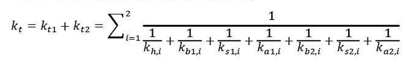
In the formula, 1 and 2 represent driving gear and driven gear respectively.