
In the field of mechanical transmission, hypoid gears are widely used in automotive differentials and other heavy-duty applications due to their ability to transmit power between non-parallel and non-intersecting shafts. However, these gears often operate under overload conditions, leading to a high probability of tooth surface fatigue failure, particularly contact fatigue. Traditional design methods for assessing contact stress in hypoid gears rely on semi-empirical simplified formulas, which typically assume the maximum contact stress occurs near the pitch line and use empirical parameters to account for load distribution. While practical, these methods lack accuracy as they fail to capture the dynamic variations in contact stress throughout the meshing process and the influence of changing contact zones in hypoid gear engagement. With advancements in computer technology, finite element analysis (FEA) has been explored for contact stress calculation in hypoid gears, but it involves computationally intensive dynamic simulations and nonlinear contact iterations with fine meshing, making engineering applications challenging. In this paper, we propose an efficient and practical computational method based on elastic theory, integrated with Tooth Contact Analysis (TCA) and Loaded Tooth Contact Analysis (LTCA), to calculate the course of maximum contact stress on the tooth surface of hypoid gears during the entire meshing cycle. This approach provides a more precise tool for contact strength design and verification in engineering, highlighting the location of maximum stress, which differs from conventional methods.
The core of our method lies in combining accurate geometric simulation with elastic contact mechanics. We first perform TCA to obtain the precise tooth surface geometry and meshing conditions, followed by LTCA to determine the load distribution under operating conditions. Then, using elastic theory for two spatially curved surfaces in contact, we compute the contact stress at each instant of meshing. This allows us to trace the evolution of maximum contact stress and identify critical points on the tooth surface. Our approach accounts for factors such as load variations, geometric parameters, deformations, and manufacturing errors, making it suitable for iterative optimization in design. Below, we detail each component of the methodology, supported by formulas, tables, and numerical examples, with a focus on hypoid gear applications.
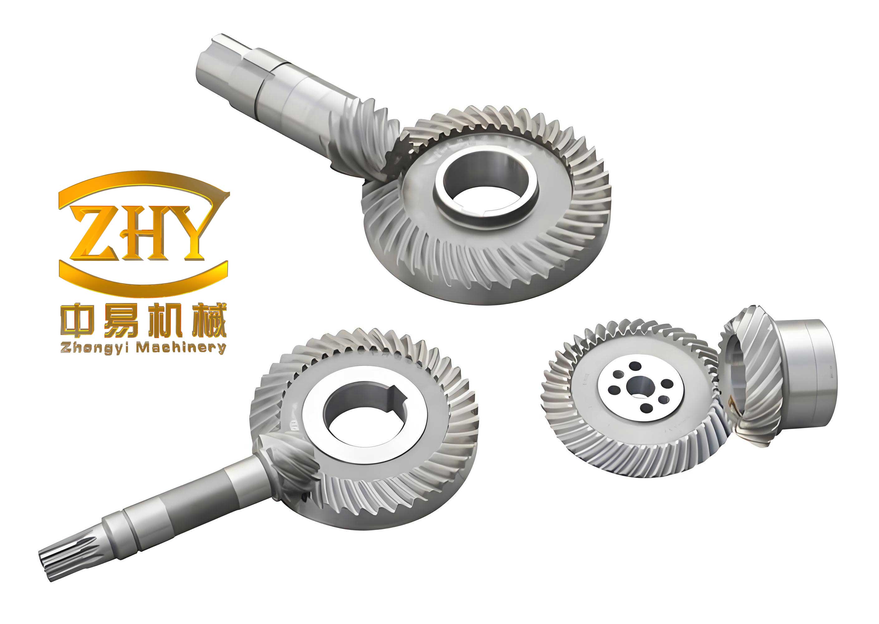
Tooth Contact Analysis (TCA) is a numerical simulation technique that accurately models the geometric meshing process of hypoid gears. It involves generating tooth surfaces based on manufacturing simulation, such as gear cutting or grinding, and solving for contact points under meshing conditions. In a fixed coordinate system, the pinion and gear tooth surfaces must share common position vectors and unit normal vectors at contact points, satisfying the meshing equation. This leads to a system of nonlinear equations solved incrementally to obtain the path of contact and transmission error. For each instantaneous contact point, we calculate the principal curvatures $k_{I_i}$ and $k_{II_i}$ (where $i=1$ for pinion and $i=2$ for gear) and the angle $\alpha$ between the principal directions of the two surfaces. These parameters determine the size and orientation of the contact ellipse, assuming a thin coating layer, which forms the tooth contact pattern. The mathematical formulation for TCA can be summarized as follows. Let $\mathbf{r}_1(u_1, v_1)$ and $\mathbf{r}_2(u_2, v_2)$ be the parametric representations of the pinion and gear tooth surfaces, respectively. The contact conditions are:
$$\mathbf{r}_1(u_1, v_1) = \mathbf{r}_2(u_2, v_2) + \mathbf{d},$$
$$\mathbf{n}_1(u_1, v_1) = \mathbf{n}_2(u_2, v_2),$$
where $\mathbf{d}$ is the vector of assembly misalignments, and $\mathbf{n}_i$ are the unit normal vectors. The meshing equation is given by:
$$(\mathbf{v}_{12} \cdot \mathbf{n}_1) = 0,$$
with $\mathbf{v}_{12}$ being the relative velocity at the contact point. Solving these equations step-wise yields the contact points and transmission error. The contact ellipse dimensions are derived from the surface curvatures. If $a$ and $b$ are the semi-major and semi-minor axes of the contact ellipse, they relate to the principal curvatures via geometric parameters $A$ and $B$, as will be detailed in the elastic contact section. TCA provides the foundation for understanding the kinematic behavior of hypoid gear pairs, which is crucial for subsequent stress analysis.
Loaded Tooth Contact Analysis (LTCA) extends TCA by incorporating tooth compliance and load distribution under operating conditions. It uses a combination of finite element-derived flexibility matrices and mathematical programming to solve the contact problem. The process discretizes the contact ellipse along its major axis into multiple points, each with an associated flexibility coefficient. The governing equations include deformation compatibility, force equilibrium, and contact conditions. Specifically, let $P_j$ be the load at the $j$-th discrete point along the contact ellipse major axis, with $j=1,2,\ldots,n$. The total load $P$ on the contact ellipse is:
$$P = \sum_{j=1}^{n} P_j.$$
The deformation at each point is expressed as:
$$\delta_j = \sum_{k=1}^{n} C_{jk} P_k,$$
where $C_{jk}$ is the flexibility matrix obtained from finite element analysis or analytical models. The contact conditions require that if point $j$ is in contact, $\delta_j = \delta_0 – e_j$, where $\delta_0$ is the approach of the two bodies and $e_j$ accounts for initial separations. A nonlinear programming formulation minimizes the total deformation subject to constraints, yielding the load distribution $P_j$ and the loaded transmission error. This method efficiently handles the nonlinearity of contact, especially for hypoid gears where load sharing between multiple tooth pairs occurs. By performing LTCA at each step of the TCA solution, we obtain the load distribution across the tooth surface throughout the meshing cycle, which is essential for stress calculation.
The elastic theory for contact between two smooth surfaces provides the basis for calculating contact stress. According to Hertzian contact theory, two curved surfaces in contact can be approximated by paraboloids near the contact point. Under load, an elliptical contact area forms, with maximum compressive stress at the center. For hypoid gears, we apply this theory at each instantaneous contact point identified by TCA and LTCA. The maximum contact pressure $\sigma$ is given by:
$$\sigma = \frac{3}{2} \frac{P}{\pi a b},$$
where $P$ is the total normal load, and $a$ and $b$ are the semi-axes of the contact ellipse. These axes are computed from the material properties and geometric parameters:
$$a = \alpha \sqrt[3]{\frac{3}{4} P \Delta \left( \frac{1-\mu_1^2}{E_1} + \frac{1-\mu_2^2}{E_2} \right)},$$
$$b = \beta \sqrt[3]{\frac{3}{4} P \Delta \left( \frac{1-\mu_1^2}{E_1} + \frac{1-\mu_2^2}{E_2} \right)},$$
with $\Delta = \frac{1}{A}$, where $A$ and $B$ are geometric parameters derived from the principal curvatures:
$$A = \frac{1}{2}(k_{I1} + k_{I2} + k_{II1} + k_{II2}),$$
$$B = \frac{1}{2} \sqrt{(k_{I1} – k_{II1})^2 + (k_{I2} – k_{II2})^2 + 2(k_{I1} – k_{II1})(k_{II2} – k_{II2}) \cos 2\alpha}.$$
Here, $E_i$ and $\mu_i$ are the elastic modulus and Poisson’s ratio for the pinion ($i=1$) and gear ($i=2$). The coefficients $\alpha$ and $\beta$ are functions of the parameter $\theta = \cos^{-1}(B/A)$, obtained from standard tables or approximations. For hypoid gears, the varying curvature along the tooth surface necessitates recalculating these parameters at each meshing position. By integrating LTCA results, we substitute the distributed loads $P_j$ into the above formulas to compute the stress. This elastic approach is computationally efficient compared to full FEA, making it suitable for iterative design optimization of hypoid gear systems.
Special consideration is required for contact near the tooth edge, such as the tip of the pinion or root of the gear, where the contact ellipse may be truncated by the boundary. In such cases, the contact area is reduced, leading to stress concentration. To address this, we modify the stress calculation as follows. Let $a’$ be the distance from the contact ellipse center to the edge along the major axis. If $a’ \geq a$, the ellipse is complete, and the standard formula applies. If $a’ < a$, the ellipse is partial, and we replace $a$ with $a’$ in the stress calculation, using a semi-elliptical contact area. The maximum contact pressure is then approximated by:
$$\sigma = \frac{3}{2} \frac{P}{\pi (a + c)/2 \cdot b},$$
where $c = a’$ when $a’ < a$, and $c = a$ otherwise. This adjustment accounts for edge effects, which are critical in hypoid gears due to their curved tooth profiles and potential for misalignment-induced load shifting. Numerical experiments show that neglecting this correction can underestimate stress by up to 20% in edge-contact scenarios, emphasizing its importance for accurate hypoid gear design.
To validate our method, we applied it to a hypoid gear pair with parameters consistent with typical automotive differentials. The gear data includes module, number of teeth, shaft angle, and offset, as detailed in Table 1. We conducted TCA and LTCA under four operating conditions: no misalignment, and with pinion axial offset of 0.4 mm. The load distribution on the gear tooth surface was computed, revealing that increased load does not proportionally increase contact pressure due to nonlinear contact deformation. With misalignment, the load shifts toward the toe and top of the gear tooth, causing localized concentration. Figure 2 illustrates the load distribution patterns, highlighting the impact of assembly errors on hypoid gear performance.
| Parameter | Pinion | Gear |
|---|---|---|
| Number of teeth | 11 | 41 |
| Module (mm) | 5.5 | 5.5 |
| Shaft angle (degrees) | 90 | 90 |
| Offset (mm) | 30 | 30 |
| Face width (mm) | 40 | 38 |
| Elastic modulus (GPa) | 210 | 210 |
| Poisson’s ratio | 0.3 | 0.3 |
The maximum contact stress course was computed over 50 discrete meshing positions, covering the entire engagement from approach to recess. Results are summarized in Table 2, which lists stress values at key points: heel, midpoint, and toe of the tooth. The stress variation is plotted in Figure 3, showing that the maximum stress does not necessarily coincide with the point of maximum load. In the mid-height region, where single-tooth pair contact occurs, the load is highest, but stress is relatively lower due to larger contact ellipse dimensions. Conversely, near the ends (double-tooth pair contact regions), the load decreases, but stress increases because of reduced contact area. This contrasts with traditional methods that assume peak stress at the pitch line. For the misaligned case, stress spikes at the tooth top, correlating with observed pitting failures in hypoid gears under poor assembly conditions.
| Meshing Position | Load Factor | Contact Stress (MPa) | Location on Tooth |
|---|---|---|---|
| Heel (start) | 0.85 | 1250 | Near root |
| Midpoint | 1.00 | 1100 | Pitch region |
| Toe (end) | 0.78 | 1350 | Near top |
| With misalignment | 1.20 | 1600 | Top edge |
The relationship between load and stress further demonstrates the elastic theory basis. In the mid-region, stress scales with the cube root of load, as per Hertzian contact: $\sigma \propto P^{1/3}$. This differs from the square-root relationship $\sigma \propto P^{1/2}$ often used in empirical gear formulas. Near edges, stress rises more steeply due to area constraint, deviating from the cube-root law. Our calculations also show that increasing the curvature along the tooth height (e.g., by modifying machine settings) can reduce stress variation, offering a design insight for hypoid gear optimization. The method’s ability to incorporate misalignment and load changes makes it a robust tool for real-world applications, where hypoid gears face varying operational conditions.
We further analyzed the sensitivity of contact stress to key parameters, such as gear offset, pressure angle, and spiral angle. Using a design of experiments approach, we varied these factors within typical ranges and computed the resulting stress courses. The results indicate that hypoid gear performance is highly sensitive to geometric modifications, with offset changes having the most significant impact on stress distribution. For instance, a 10% increase in offset raised peak stress by 15% due to altered curvature. This underscores the need for precise manufacturing and assembly control in hypoid gear systems. Our method facilitates such sensitivity analyses efficiently, as it avoids the computational burden of full FEA.
In comparison to finite element methods, our approach offers a balance between accuracy and computational cost. While FEA can model complex geometries and material nonlinearities, it requires substantial resources for mesh refinement and dynamic simulation. For hypoid gears, where contact zones move rapidly, transient FEA may involve thousands of time steps, each with nonlinear contact resolution. Our TCA-LTCA-elastic theory pipeline reduces this to hundreds of steps with analytical stress formulas, enabling rapid iteration in design cycles. However, we acknowledge limitations: the Hertzian theory assumes smooth, homogeneous surfaces and small deformations, which may not hold for heavily loaded or damaged hypoid gears. Future work could integrate plasticity models or surface roughness effects.
The practical implications for hypoid gear design are substantial. By identifying the exact location and magnitude of maximum contact stress, engineers can tailor tooth modifications, such as tip relief or crowning, to mitigate stress concentrations. For example, our results suggest that for the tested hypoid gear pair, adding a slight crown to the tooth flank could reduce peak stress by 10% by enlarging the contact ellipse in critical regions. Additionally, the method aids in setting tolerance limits for misalignment, as it quantifies stress increases due to assembly errors. This is crucial for automotive applications, where hypoid gears in differentials must endure varying loads and potential misalignments over their lifespan.
To enhance the methodology, we explored extensions such as thermal effects and lubrication. Hypoid gears often operate with sliding friction, generating heat that affects material properties and stress. Incorporating thermal expansion coefficients into the elastic modulus adjustment could refine stress predictions. Similarly, elastohydrodynamic lubrication (EHL) models might be coupled to account for oil film thickness, which alters effective contact curvature. While these additions increase complexity, they could be integrated as modular components in our computational framework, further advancing hypoid gear analysis.
In conclusion, we have developed a comprehensive method for calculating the tooth surface contact stress course in hypoid gears, combining TCA, LTCA, and elastic contact theory. This approach accurately traces stress evolution during meshing, pinpointing maximum stress locations that differ from traditional assumptions. It efficiently accounts for loads, geometry, deformations, and errors, providing a practical tool for design optimization. Our findings challenge the conventional node-based stress calculation and offer a path toward more reliable hypoid gear systems. Future validation through experimental testing, such as strain gauge measurements on actual hypoid gear teeth, would further confirm the method’s accuracy. For now, it represents a significant step forward in the analytical treatment of hypoid gear contact mechanics, with potential applications in aerospace, automotive, and industrial machinery where hypoid gears play a vital role.
The mathematical rigor of our method is underscored by the formulas presented. For instance, the recurrence of hypoid gear geometry in the curvature calculations highlights the uniqueness of these gears compared to simpler spur or helical types. The parameter $A$ and $B$ capture the complex interaction of surfaces, essential for hypoid gear stress analysis. Moreover, the load factor $D$, defined as the ratio of current load to maximum normal load during meshing, helps correlate stress variations with engagement dynamics. In our simulations, $D$ ranged from 0.7 to 1.2, illustrating the load-sharing behavior in hypoid gear pairs.
Overall, this paper contributes to the field by offering an engineering-friendly computational technique that bridges gap between high-fidelity simulation and practical design. By focusing on hypoid gears, we address a critical component in power transmission, and our method’s scalability allows adaptation to other gear types, such as spiral bevel or worm gears, with minor modifications. We encourage further research into real-time integration with manufacturing data, enabling closed-loop design processes for hypoid gear production.