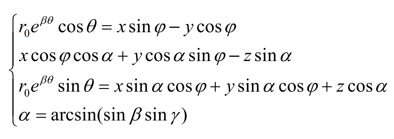
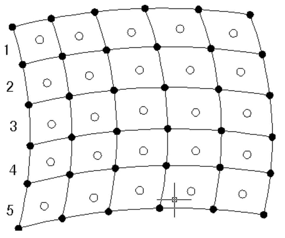
The tooth surface data point coordinates of logarithmic spiral bevel gear are collected by 3D laser scanner, and the tooth surface of logarithmic spiral bevel gear is reconstructed. When comparing and analyzing the errors between the real tooth surface and the theoretical tooth surface of logarithmic spiral bevel gear, some discrete data points for constructing the tooth surface of logarithmic spiral bevel gear should be calculated. However, these discrete data points are not given grid intersections, because the data points passing through the fixed grid intersection have been interpolated when constructing the tooth surface of logarithmic spiral bevel gear, and the error is zero. Therefore, the calculated discrete data points are located in the middle of the grid points, as shown in Figure. In the figure, “●” represents the data points of the given grid intersection, and “O” represents the data points of the obtained non-given grid intersection.
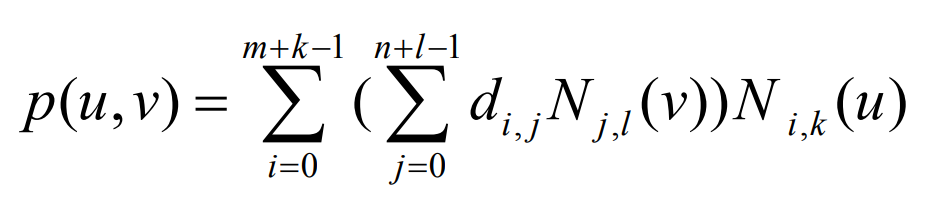
Given the original control vertex on the tooth surface of the constructed logarithmic spiral bevel gear, the number k and the node vector (U, V), the parameter equation of the k-th B-spline tooth surface is defined as:
Given a pair of parameter values (U, V) in the defined domain of the tooth surface of the logarithmic spiral bevel gear, in order to find the corresponding point P (U, V) on the tooth surface of the logarithmic spiral bevel gear, the debour recursive calculation method can be carried out along any parameter direction.
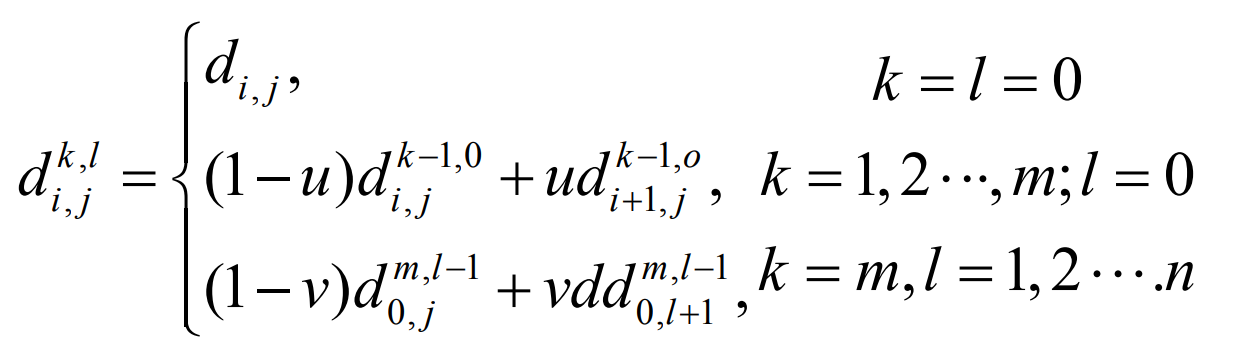
When calculating according to the above algorithm, the U parameter value first performs M-level recursion of the curve for N + 1 polygons along the U direction of the control mesh, and then obtains n + 1 vertices along the V direction. Then the recursive algorithm of the curve is performed on it with the value of V parameter. The algorithm shows that each intermediate vertex is the line interpolation of the two vertices of the previous level. After N-level recursion, a point is obtained, that is, the discrete data points on the constructed surface.
For error analysis, it is assumed that the coordinate values of Y0 and Z0 of the obtained discrete data point P0 (x0, Y0, Z0) are equal to the coordinate values of the theoretical tooth surface of the logarithmic spiral bevel gear, and then y’0 and Z’0 are substituted into the theoretical tooth surface equation of the logarithmic spiral bevel gear: