
The rolling mill gear shaft with grinding cracks is made of 17CrNiMo6 steel, the modulus Mn is 18mm, the carburizing and quenching process requirements are that the carburizing layer depth is 3.30 ~ 3.70mm, and the surface hardness is 58.0 ~ 62.0hrc. The processing flow is normalizing after forging → rough turning → quenching and tempering → semi finish turning → gear hobbing → carburizing and quenching → shot peening → finish turning → gear grinding.
1. Macro analysis
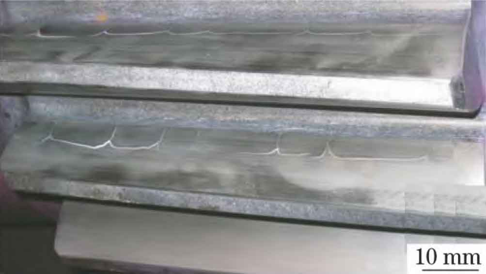
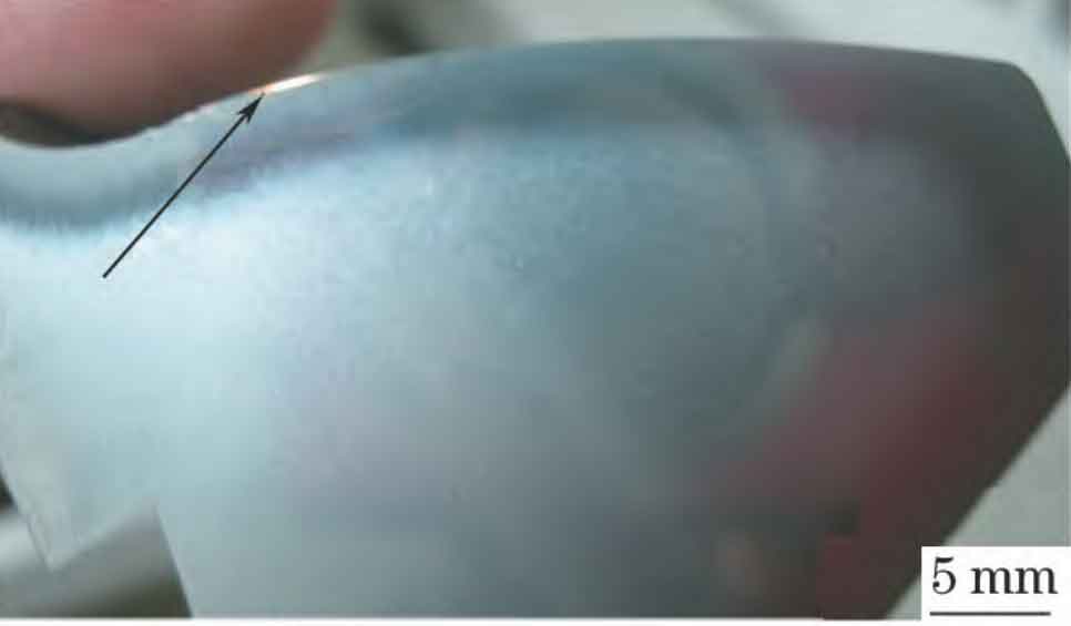
After grinding the gear shaft of the rolling mill, it is found that there are nail cap or turtle back shaped convex cracks on the tooth surface during placement, and the serious parts can be tilted by hand, as shown in Fig. 1. Crescent shaped grinding burn white bright layer and dark grinding tempering layer are found at the crack on the tooth surface, as shown in Fig. 2. The maximum depth of grinding white bright layer is 0.25mm, the length is 3.60mm, and the depth of grinding tempering layer is 1.00mm.
2. Chemical composition analysis
The chemical composition of the gear shaft matrix is analyzed by arl3460 direct reading spectrometer. The results are shown in the table. It can be seen that the chemical composition of the matrix meets the requirements of 17CrNiMo6 steel in alloy structural steel (GB / t3077-2015). At the same time, the carbon content of the tooth surface of the gear shaft of the rolling mill is determined, and the result is 0.81% (mass fraction), which meets the requirements of the standard.
3. Non metallic inclusion inspection
Samples were taken from the grinding cracks on the gear shaft of the rolling mill for non-metallic inclusion inspection. The results showed that the fine system: a0.5, B0, C0, d0.5, and the coarse system: a0e, b0e, c0e, D0E. It can be seen that the non-metallic inclusions in the raw materials of the gear shaft did not exceed the standard.
4. Microanalysis
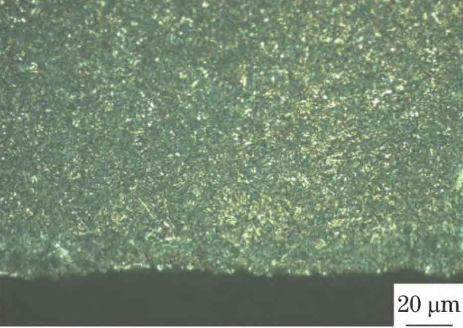
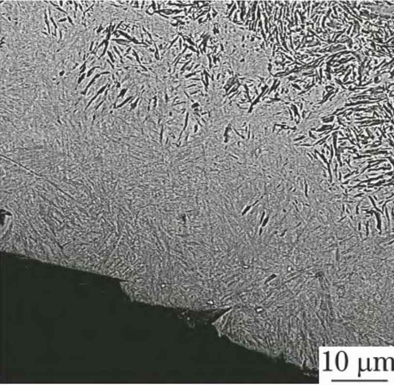
The optical microscope is used to carry out metallographic inspection on the intact tooth surface without crack. The results are shown in Figure 3. It can be seen that the microstructure is fine acicular martensite + a small amount of residual austenite + dispersed fine granular carbide, which is based on metallographic inspection for carburization of heavy duty gears (JB / t6141.3-1992) The results are grade 2 of martensite + retained austenite and grade 1 ~ 2 of surface carbide, which all meet the requirements of the standard.
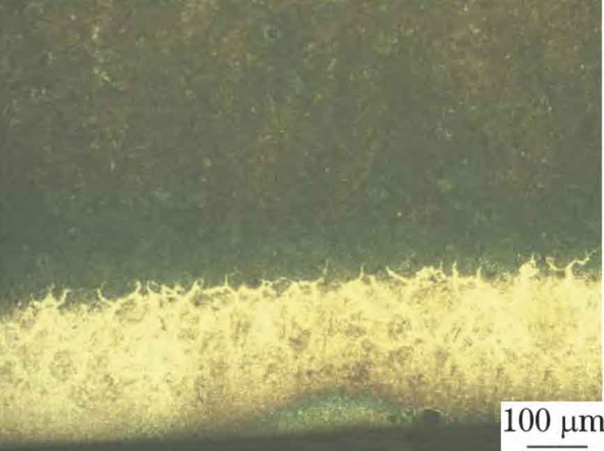
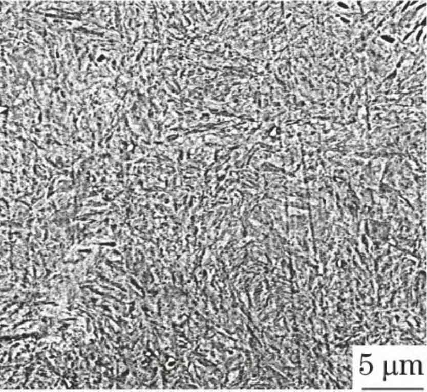
The morphology of white bright layer at grinding crack is shown in Fig. 4. In order to further confirm the microstructure of the white bright layer, phenomxl desktop scanning electron microscope (SEM) was used to analyze it. It can be seen that the microstructure of the white bright layer is quenched cryptocrystalline martensite under rapid heating and cooling. The SEM morphology is shown in Fig. 5.
5. Hardness test
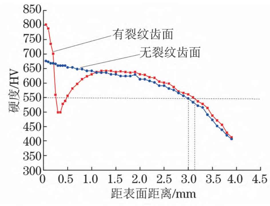
The hardness gradient test was carried out on the tooth surface without grinding crack and the tooth surface with grinding crack respectively. The hardness gradient curve is shown in Fig. 6. The hardness gradient curve of the tooth surface with grinding crack shows the characteristics of high (white bright layer) – low (dark grinding tempering layer) – high (normal infiltration layer structure), indicating that there is a grinding burn layer, which is consistent with the macroscopic and microstructure characteristics. The grinding allowance is 0.40mm. After grinding, the effective hardened layer depth of carburizing and quenching of rolling mill gear shaft is 3.00 ~ 3.10mm, and the carburizing and quenching process layer depth is qualified.
The gear shaft of the rolling mill in the case is grinded by the forming gear grinding machine and processed by 3sg60 grinding wheel. In the early grinding process, the part above the gear indexing circle does not participate in the cutting process, while the cutting removal amount below the indexing circle, especially at the upper end of the hob transition arc, is large. At the same time, the feed rate is large during rough grinding, and the same tooth groove needs to be ground for many times, which is easy to cause problems such as carburizing quenching, tooth surface tempering, secondary quenching and so on.
During rough grinding, the feed rate of the original process is 0.100mm, and there are no grinding burns, grinding cracks and other phenomena in similar workpieces. Through consulting the on-site production records, it is found that in order to ensure the delivery period, the feed rate during rough grinding of the gear shaft is increased to 0.180mm. In order to ensure that the accuracy and surface roughness meet the standard, the feed rate during fine grinding remains unchanged. The increase of feed rate during rough grinding results in too high grinding heat and high grinding local temperature, exceeding the phase transformation point AC1. After quenching with coolant, the surface layer forms an untempered secondary quenching white layer with high hardness and brittleness, and the carburized layer finally forms a typical hardness distribution characteristic of high low high grinding quenching burn. The parts with excessive cutting amount in the early stage are mainly concentrated below the indexing circle of the tooth surface, so the grinding burn is mainly concentrated at this position. Cracks will occur when the stress on the grinding surface of the gear shaft is greater than its breaking strength.
Therefore, the grinding cracks of the gear shaft of the rolling mill are mainly located below the indexing circle of the tooth surface, as shown in Fig. 1 and Fig. 2. After the grinding crack was found on the gear shaft, the grinding processing of the subsequent five parts of the batch was suspended, the feed rate during rough grinding was changed to 0.120mm, and stress relief tempering was carried out within 2h after rough grinding. The five gear shafts were subjected to metallographic inspection, and there were no grinding burns.