
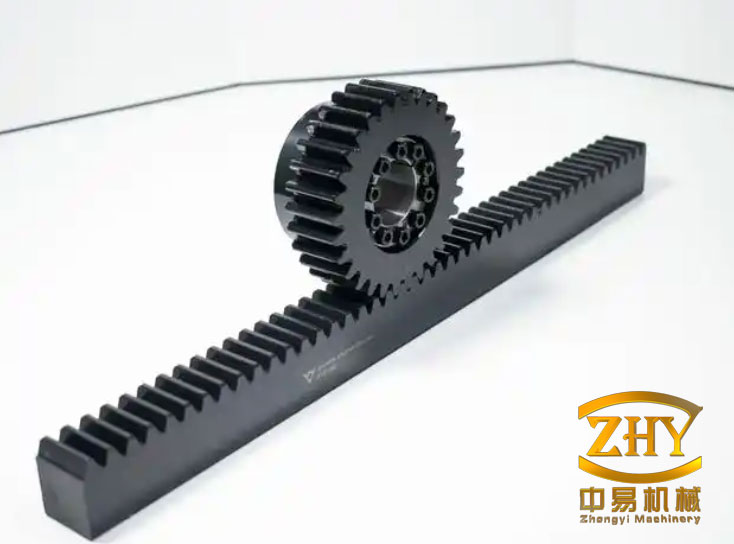
In this design project, I focused on the numerical calculation, strength verification, and three-dimensional parametric modeling of rack and pinion gears for a passenger-car steering system. The rapid improvement of automotive design methods has made advanced three-dimensional platforms such as CATIA, UG, and Proe very common in product development. I used CATIA as the main modeling environment because it allows me to connect formulas, tables, law curves, and geometric features in a single associative model. The central object of my work is a set of rack and pinion gears used in a steering gear, where the pinion is a small helical gear and the rack is a linear gear with equivalent module and pressure angle. By building the rack and pinion gears parametrically, I can update the complete model when the module, tooth number, helix angle, or rack length changes. This approach is useful for later motion simulation, structural analysis, and the creation of a reusable library of rack and pinion gears.
1. Design Context and Technical Specifications
I started the design from the main vehicle parameters because the steering load, the pinion torque, and the rack force all depend on the front-axle load, the tire pressure, the steering ratio, and the number of steering-wheel turns. The steering system must keep or change the vehicle direction, and the rack and pinion gears are the core transmission pair in the steering gear. I selected a passenger-car configuration with the following main technical parameters.
| Parameter | Symbol | Value | Unit |
|---|---|---|---|
| Maximum power | $$P_{\max}$$ | 100 | kW |
| Maximum torque | $$T_{\max}$$ | 220 | N·m |
| Vehicle width | $$B$$ | 1811 | mm |
| Vehicle height | $$H$$ | 1453 | mm |
| Wheelbase | $$L$$ | 2920 | mm |
| Front track | $$B_f$$ | 1531 | mm |
| Curb mass | $$m_c$$ | 1540 | kg |
| Steering-system angular ratio | $$i_w$$ | 20 | — |
| Total steering-wheel turns | $$n_{sw}$$ | 4 | turns |
The steering-system angular ratio for passenger cars is usually selected between 17 and 25. I initially selected an angular ratio of 20. This value is a compromise between steering effort and steering response. A lower ratio makes the steering faster but increases the driver effort, while a higher ratio reduces effort but requires more steering-wheel rotation for a given road-wheel angle. For the rack and pinion gears, this ratio directly influences the pinion torque and the rack force. I also used the total steering-wheel turns to estimate the number of rack teeth and the total rack travel.
2. Standstill Steering Resistance and Actuation Torque
When the vehicle is stationary on asphalt or concrete, the tire contact patch must overcome a large resisting moment before the road wheels turn. I calculated the standstill steering resistance moment using the empirical formula for rack and pinion gears and steering systems. This moment is the basis for the pinion torque and the steering-wheel force.
$$M_R = \frac{f}{3}\sqrt{\frac{G_1^3}{p}}$$
In this equation, $$M_R$$ is the standstill steering resistance moment in N·mm, $$f$$ is the sliding friction coefficient between the tire and the ground, $$G_1$$ is the steering-axle load in N, and $$p$$ is the tire pressure in MPa. I used a friction coefficient of 0.7, which is a common value for dry asphalt or concrete. The steering-axle load was calculated from the vehicle mass and an additional passenger load.
$$G_1 = 0.55G = 0.55(1540 + 5 \times 75) \times 9.8 = 10321.85 \text{ N}$$
The tire pressure was selected as 0.22 MPa. Substituting these values into the empirical formula gave the standstill resistance moment.
$$M_R = \frac{0.7}{3}\sqrt{\frac{10321.85^3}{0.22}} = 521677.08 \text{ N}\cdot\text{mm}$$
This value is large because the tire must be twisted in place. For rack and pinion gears, this resistance moment is transformed into pinion torque through the steering ratio and the positive transmission efficiency. I then calculated the steering-wheel operating force using the geometry of the steering linkage and the steering gear.
$$F_h = \frac{2 L_1 M_R}{L_2 D_{sw} i_w \eta_+}$$
Here, $$L_1$$ is the steering-arm length, $$L_2$$ is the steering-knuckle-arm length, $$D_{sw}$$ is the steering-wheel diameter, $$i_w$$ is the steering-gear angular ratio, and $$\eta_+$$ is the forward transmission efficiency. For rack and pinion gears, the forward efficiency is usually about 0.9. The ratio $$L_1 / L_2$$ is commonly between 0.85 and 1.1, and I treated it as approximately 1. The steering-wheel diameter was 0.4 m. Using the baseline calculation from the selected rack and pinion gears arrangement, the steering-wheel force was about 193021 N under the assumed linkage ratio. This high value indicates that a direct mechanical steering system without assistance would be difficult for the driver, so the rack and pinion gears must be combined with a suitable assistance strategy in a real vehicle.
The torque on the pinion shaft is one of the most important outputs of this stage. For rack and pinion gears, the pinion torque is obtained from the resistance moment divided by the angular ratio and the forward efficiency.
$$T_1 = \frac{M_R}{\eta_+ i_w}$$
$$T_1 = \frac{521677.08}{0.9 \times 20} = 28982.06 \text{ N}\cdot\text{mm} = 28.98 \text{ N}\cdot\text{m}$$
This pinion torque is used in the bending strength and contact strength calculations of the rack and pinion gears. It is also used to determine the minimum shaft diameter and to check the combined bending and torsional stress of the pinion shaft.
3. Preliminary Selection of Rack and Pinion Gears
For the rack and pinion gears in a passenger-car steering gear, the module range is generally 2 mm to 3 mm. The driving pinion usually has a small number of teeth, commonly between 5 and 9. Because the pinion tooth number is small, a helical gear form is often used to improve meshing smoothness and load capacity. I initially selected a pinion tooth number of 8, a normal pressure angle of 20°, and a helix angle of 12°. The helix angle range for helical rack and pinion gears is usually 9° to 12°, so 12° is at the upper end of the common range and provides good overlap without introducing excessive axial force.
| Design Item | Symbol | Initial Choice | Unit |
|---|---|---|---|
| Normal module | $$m_n$$ | 3 | mm |
| Normal pressure angle | $$\alpha_n$$ | 20 | ° |
| Helix angle | $$\beta$$ | 12 | ° |
| Pinion tooth number | $$z_1$$ | 8 | — |
| Rack tooth number | $$z_2$$ | 32 | — |
| Face width | $$b$$ | 40 | mm |
| Rack bar diameter | $$d_r$$ | 32 | mm |
| Rack length | $$L_r$$ | 524 | mm |
The rack tooth number was estimated from the total steering-wheel turns and the pinion tooth number. For rack and pinion gears, one complete pinion revolution moves the rack by one circular pitch distance along the pitch line. Therefore, the rack tooth number is related to the total number of steering-wheel turns.
$$z_2 = n_{sw} z_1 = 4 \times 8 = 32$$
I selected a circular-end rack in this design because it reduces stress concentration and fits the packaging requirements of the steering gear. The rack bar diameter was chosen as 32 mm because the vehicle load is relatively high. Common passenger-car rack bar diameters include 22 mm, 26 mm, 30 mm, and 32 mm. The larger diameter increases bending stiffness and improves the strength of the rack and pinion gears under steering loads.
4. Allowable Stress and Fatigue Life
Before checking the bending and contact strength of the rack and pinion gears, I determined the allowable stresses. The pinion and rack materials must resist repeated loading during steering operations. I used contact fatigue limits and bending fatigue limits, together with life factors and a safety factor.
| Property | Symbol | Pinion Value | Rack Value | Unit |
|---|---|---|---|---|
| Contact fatigue limit | $$\sigma_{H\lim}$$ | 1500 | 300 | MPa |
| Bending fatigue limit | $$\sigma_{FE}$$ | 550 | 500 | MPa |
| Contact life factor | $$K_{HN}$$ | 1.5 | 1.5 | — |
| Bending life factor | $$K_{FN}$$ | 2 | 2 | — |
| Safety factor | $$S$$ | 1 | 1 | — |
The stress cycle number was calculated from the pinion speed, the number of load applications per revolution, and the expected service life. I used a design life based on 10 years, 8 working hours per day, and 300 working days per year.
$$N_1 = 60 n_1 j L_h = 60 \times 15 \times 1 \times (10 \times 8 \times 300) = 2.16 \times 10^7$$
$$N_2 = \frac{N_1}{i} = \frac{2.16 \times 10^7}{4} = 5.4 \times 10^6$$
Using the life factors and a failure probability of 1%, I calculated the allowable contact and bending stresses. For the pinion, the allowable contact stress was much higher than the allowable bending stress, which is typical for hardened gear materials.
$$[\sigma_H]_1 = \frac{K_{HN}\sigma_{H\lim 1}}{S} = \frac{1500 \times 1.5}{1} = 2250 \text{ MPa}$$
$$[\sigma_H]_2 = \frac{K_{HN}\sigma_{H\lim 2}}{S} = \frac{300 \times 1.5}{1} = 450 \text{ MPa}$$
$$[\sigma_F]_1 = \frac{K_{FN}\sigma_{FE1}}{S} = \frac{550 \times 2}{1} = 1100 \text{ MPa}$$
$$[\sigma_F]_2 = \frac{K_{FN}\sigma_{FE2}}{S} = \frac{500 \times 2}{1} = 1000 \text{ MPa}$$
For the contact strength check, I used the smaller allowable contact stress when comparing the pinion and rack. However, because the pinion is the critical member in many rack and pinion gears, I also checked the pinion separately. The average allowable contact stress used in the baseline calculation was 2100 MPa, based on the pinion-dominated contact condition.
5. Bending Strength Design of Rack and Pinion Gears
The bending strength design determines the minimum normal module required for the rack and pinion gears. I used the standard helical gear bending formula and included the helix-angle influence factor, the form factor, the stress correction factor, the face-width coefficient, the transverse contact ratio, and the allowable bending stress.
$$m_n \ge \sqrt[3]{\frac{2 K T_1 Y_\beta \cos^2 \beta \, Y_{Fa} Y_{Sa}}{\phi_d Z_1^2 \epsilon_\alpha [\sigma_F]}}$$
The load factor was calculated from the application factor, the dynamic factor, the transverse load-distribution factor, and the face load-distribution factor.
$$K = K_A K_V K_{F\alpha} K_{F\beta}$$
I used an application factor of 1, a dynamic factor of 1.2, a transverse load-distribution factor of 1.2, and a face load-distribution factor of 1.3. The resulting load factor was 1.872.
$$K = 1 \times 1.2 \times 1.2 \times 1.3 = 1.872$$
The longitudinal contact ratio was calculated as follows.
$$\epsilon_\beta = 0.318 \phi_d Z_1 \tan \beta = 0.318 \times 2 \times 8 \times \tan 12^\circ = 1.08$$
The helix-angle influence factor was 0.88, and the transverse contact ratio was 1.25. The equivalent tooth numbers for the pinion and rack were calculated using the helix angle.
$$Z_{v1} = \frac{Z_1}{\cos^3 \beta} = \frac{8}{\cos^3 12^\circ} = 8.56$$
$$Z_{v2} = \frac{Z_2}{\cos^3 \beta} = \frac{32}{\cos^3 12^\circ} = 34.19$$
For the pinion, the form factor was 3.51 and the stress correction factor was 1.43. For the rack, the form factor was 2.52 and the stress correction factor was 1.63. I compared the product divided by allowable bending stress for both members.
$$\frac{Y_{Fa1} Y_{Sa1}}{[\sigma_F]_1} = \frac{3.51 \times 1.43}{1100} = 0.0046$$
$$\frac{Y_{Fa2} Y_{Sa2}}{[\sigma_F]_2} = \frac{2.52 \times 1.63}{1000} = 0.0041$$
The pinion had the larger value, so the pinion is the critical member for bending strength in these rack and pinion gears. Substituting all values into the bending formula gave a minimum normal module of 1.38 mm. I selected a normal module of 3 mm, which is well above the minimum and provides a robust design margin.
$$m_n \ge 1.38 \text{ mm} \Rightarrow m_n = 3 \text{ mm}$$
6. Contact Strength Check of Rack and Pinion Gears
After the bending design, I checked the contact strength of the rack and pinion gears. The contact stress must not exceed the allowable contact stress, otherwise pitting may occur on the tooth flanks. I used the following contact stress formula for helical gears.
$$\sigma_H = \sqrt{\frac{2 F_t}{b d_1 \epsilon_\alpha} \cdot \frac{\mu + 1}{\mu}} \, Z_H Z_E \le [\sigma_H]$$
In this equation, $$F_t$$ is the transverse tangential force, $$b$$ is the face width, $$d_1$$ is the pinion pitch diameter, $$\mu$$ is the gear ratio, $$Z_H$$ is the zone factor, and $$Z_E$$ is the elastic factor. For the rack and pinion gears, the rack can be treated as a gear with an infinite number of teeth, so the ratio term becomes close to 1. I used a zone factor of 2.43 and an elastic factor of 189.8 MPa$$^{1/2}$$. The load factor for contact stress was calculated from the application factor, dynamic factor, transverse load-distribution factor, and face load-distribution factor.
$$K = K_A K_V K_{H\alpha} K_{H\beta} = 1 \times 1.2 \times 1.2 \times 1.417 = 2.04$$
The tangential force was obtained from the pinion torque and the pitch diameter.
$$F_t = \frac{2 T_1}{d_1} = \frac{2 \times 28979.97}{24.54} = 2269.38 \text{ N}$$
Substituting the values into the contact stress formula gave a calculated contact stress of 1367.5 MPa. This is lower than the allowable contact stress of 2100 MPa, so the rack and pinion gears satisfy the contact fatigue strength requirement.
$$\sigma_H = 1367.5 \text{ MPa} \le [\sigma_H] = 2100 \text{ MPa}$$
Therefore, the selected module, tooth number, helix angle, and face width satisfy both the bending fatigue strength and the contact fatigue strength requirements. The rack and pinion gears can transmit the required steering torque without immediate risk of tooth breakage or surface pitting under the assumed load spectrum.
7. Geometric Parameters of the Pinion and Rack
Once the module and tooth number were confirmed, I calculated the complete geometry of the pinion and rack. The pinion is a helical gear with a normal module of 3 mm, a normal pressure angle of 20°, a helix angle of 12°, and 8 teeth. The pitch diameter, addendum, dedendum, whole depth, tip diameter, root diameter, clearance, and face width are summarized below.
| Name | Symbol | Formula | Result |
|---|---|---|---|
| Normal module | $$m_n$$ | — | 3 mm |
| Helix angle | $$\beta$$ | — | 12° |
| Tooth number | $$z$$ | — | 8 |
| Normal pressure angle | $$\alpha_n$$ | — | 20° |
| Normal circular pitch | $$p_n$$ | $$p_n = \pi m_n$$ | 9.42 mm |
| Pitch diameter | $$d$$ | $$d = \frac{m_n z}{\cos \beta}$$ | 24.54 mm |
| Addendum | $$h_a$$ | $$h_a = m_n$$ | 3 mm |
| Dedendum | $$h_f$$ | $$h_f = 1.25 m_n$$ | 3.75 mm |
| Whole depth | $$h$$ | $$h = h_a + h_f$$ | 6.75 mm |
| Tip diameter | $$d_a$$ | $$d_a = d + 2 h_a$$ | 30.54 mm |
| Root diameter | $$d_f$$ | $$d_f = d – 2 h_f$$ | 18.04 mm |
| Clearance | $$c$$ | $$c = 0.25 m_n$$ | 0.75 mm |
| Face width | $$b$$ | $$b = \phi_d d + (5 \sim 10)$$ | 40 mm |
For the rack, the module, pressure angle, and helix angle must match the pinion. The helix direction is opposite to that of the pinion so that the rack and pinion gears mesh correctly. The rack tooth number is 32, and the total rack length is 524 mm. I selected a round rack bar with a diameter of 32 mm. This diameter gives sufficient bending stiffness and allows the rack to be supported and guided inside the steering gear housing.
| Rack Parameter | Symbol | Value | Unit |
|---|---|---|---|
| Normal module | $$m_n$$ | 3 | mm |
| Normal pressure angle | $$\alpha_n$$ | 20 | ° |
| Helix angle | $$\beta$$ | 12 | ° |
| Rack tooth number | $$z_2$$ | 32 | — |
| Rack bar diameter | $$d_r$$ | 32 | mm |
| Total rack length | $$L_r$$ | 524 | mm |
The total rack travel for four steering-wheel turns can be estimated from the pinion pitch diameter. For rack and pinion gears, one pinion revolution moves the rack by the pitch circumference.
$$s = \pi d = \pi \times 24.54 = 77.09 \text{ mm}$$
$$S_{total} = n_{sw} s = 4 \times 77.09 = 308.36 \text{ mm}$$
This travel is less than the total rack length of 524 mm, which leaves enough room for the rack housing, the assistance mechanism, and the end stops. The rack and pinion gears therefore satisfy the packaging requirement of the steering gear.
8. Pinion Shaft Design and Stress Analysis
The pinion shaft carries the steering torque and also experiences bending from the tangential, radial, and axial forces of the rack and pinion gears. I first determined the minimum shaft diameter from the torsional strength requirement.
$$\tau_T = \frac{T}{W_T} = \frac{T}{0.2 d^3} \le [\tau_T]$$
Using a pinion torque of 28979.97 N·mm and an allowable torsional stress of 100 MPa, the minimum diameter was calculated as follows.
$$d \ge \sqrt[3]{\frac{T}{0.2 [\tau_T]}} = \sqrt[3]{\frac{28979.97}{0.2 \times 100}} = 11.32 \text{ mm}$$
I selected a minimum shaft diameter of 15 mm to provide a margin for keyways, shoulders, bearings, and manufacturing tolerances. The pinion shaft then was checked under combined bending and torsion. The forces acting on the pinion are the tangential force, the radial force, and the axial force.
$$F_t = \frac{2T}{d} = \frac{2 \times 28979.97}{24.54} = 2269.38 \text{ N}$$
$$F_r = \frac{F_t \tan \alpha_n}{\cos \beta} = \frac{2269.38 \times \tan 20^\circ}{\cos 12^\circ} = 844.44 \text{ N}$$
$$F_a = F_t \tan \beta = 2269.38 \times \tan 12^\circ = 482.37 \text{ N}$$
These three force components are typical for helical rack and pinion gears. The axial force is caused by the helix angle and must be carried by the bearings. I then calculated the support reactions in the vertical and horizontal planes. The bearing span and the force positions were based on the shaft layout.
| Force | Symbol | Value | Unit |
|---|---|---|---|
| Tangential force | $$F_t$$ | 2269.38 | N |
| Radial force | $$F_r$$ | 844.44 | N |
| Axial force | $$F_a$$ | 482.37 | N |
In the vertical plane, the left bearing reaction was calculated from the radial force and the moment produced by the axial force. In the horizontal plane, the left bearing reaction was calculated from the tangential force.
$$F_{RAV} = \frac{l_2 F_r + F_a \frac{d_1}{2}}{l_1 + l_2} = 544.52 \text{ N}$$
$$F_{RBV} = F_r – F_{RAV} = 266.91 \text{ N}$$
$$F_{RAH} = \frac{F_t l_2}{l_1 + l_2} = 1349.36 \text{ N}$$
$$F_{RBH} = F_t – F_{RAH} = 920.02 \text{ N}$$
The resultant bearing reactions were then used to find the bending moments along the shaft. Because the steering gear can rotate in both directions, I treated the stress as fully reversed and used a fatigue strength reduction factor. The bending section modulus for the solid circular shaft was calculated as follows.
$$W \approx \frac{\pi d^3}{32} = \frac{\pi \times 24.54^3}{32} = 1450.4 \text{ mm}^3$$
The equivalent stress under combined bending and torsion was calculated using the von Mises-type formula.
$$\sigma_e = \frac{\sqrt{M^2 + (\alpha T)^2}}{W}$$
I used a torsion-to-bending conversion factor of 1.5. Substituting the maximum bending moment and torque gave an equivalent stress of 37.67 MPa. The allowable fatigue stress for the selected shaft material was 70 MPa. Therefore, the pinion shaft design is safe.
$$\sigma_e = 37.67 \text{ MPa} \le [\sigma_{-1b}] = 70 \text{ MPa}$$
This check confirms that the pinion shaft can withstand the combined loading from the rack and pinion gears under the assumed steering conditions. The minimum diameter of 15 mm is also sufficient from a manufacturing point of view, because it allows standard bearings and seals to be selected.
9. Parametric Modeling of Rack and Pinion Gears in CATIA
After completing the numerical design, I built the rack and pinion gears in CATIA using a parametric approach. The main advantage of this method is that the geometry is driven by formulas. When I change the module, tooth number, helix angle, or face width, the pinion and rack update automatically. This is especially useful for rack and pinion gears because their geometry is defined by a small set of primary parameters.
| CATIA Parameter | Symbol | Value | Unit |
|---|---|---|---|
| Normal module | $$m_n$$ | 3 | mm |
| Normal pressure angle | $$\alpha_n$$ | 20 | ° |
| Helix angle | $$\beta$$ | 12 | ° |
| Pinion tooth number | $$z_1$$ | 8 | — |
| Rack tooth number | $$z_2$$ | 32 | — |
| Face width | $$b$$ | 40 | mm |
| Pitch diameter | $$d_1$$ | 24.54 | mm |
| Addendum | $$h_a$$ | 3 | mm |
| Dedendum | $$h_f$$ | 3.75 | mm |
| Rack length | $$L_r$$ | 524 | mm |
In the CATIA model, I used the Generative Shape Design environment to create the involute profile of the pinion. The involute curve of a helical gear is generated from the base circle. The base radius is related to the pitch radius and the transverse pressure angle.
$$r = \frac{m_n z_1}{2 \cos \beta}$$
$$r_b = r \cos \alpha_t$$
$$\tan \alpha_t = \frac{\tan \alpha_n}{\cos \beta}$$
The involute curve can be described by two parametric equations. I created two law curves in CATIA, one for the x-coordinate and one for the y-coordinate.
$$x = r_b (\cos t + t \sin t)$$
$$y = r_b (\sin t – t \cos t)$$
The parameter $$t$$ controls the position along the involute. I generated the tooth flank by combining the involute curve with the root fillet and the tip arc. Then I mirrored the flank to create one complete tooth. The tooth pattern was repeated around the pinion axis using a circular pattern with 8 instances. The helical form was created by sweeping the tooth profile along a helix with a 12° helix angle. Finally, I added the hub, the shaft, the bearing shoulders, and the keyway features.
For the rack, I started from the same normal module, pressure angle, and helix angle. The rack tooth profile is essentially a straight-sided profile in the normal plane. I created the rack pitch line, the addendum line, and the dedendum line, and then generated the rack teeth by a linear pattern. The rack was modeled as a round bar with a diameter of 32 mm and a total length of 524 mm. I used the same pitch and pressure angle as the pinion so that the rack and pinion gears mesh correctly in the assembly.
After creating the pinion and rack as separate parts, I assembled the rack and pinion gears in the CATIA Assembly Design workbench. I applied a coincidence constraint between the pinion pitch circle and the rack pitch line, and I aligned the helix directions. I also used a contact constraint or a gear constraint to verify that the pinion rotation produces the correct rack translation. This assembly is the basis for further motion simulation and interference checking. The parametric links between the parts mean that the assembly updates when the primary parameters change.
10. Detailed Parameter Relationships for Rack and Pinion Gears
To make the CATIA model robust, I defined all secondary parameters from the primary parameters. This is important for rack and pinion gears because many dimensions depend on the module, tooth number, and helix angle. The following relationships were implemented in the formula editor.
| Secondary Parameter | Formula | Purpose |
|---|---|---|
| Transverse module | $$m_t = \frac{m_n}{\cos \beta}$$ | Defines the transverse pitch |
| Transverse pressure angle | $$\tan \alpha_t = \frac{\tan \alpha_n}{\cos \beta}$$ | Defines the involute base circle |
| Pitch diameter | $$d = \frac{m_n z}{\cos \beta}$$ | Defines the pitch circle |
| Base diameter | $$d_b = d \cos \alpha_t$$ | Defines the involute generation circle |
| Addendum diameter | $$d_a = d + 2 m_n$$ | Defines the outer diameter |
| Root diameter | $$d_f = d – 2.5 m_n$$ | Defines the root circle |
| Normal circular pitch | $$p_n = \pi m_n$$ | Defines the rack tooth spacing |
| Transverse circular pitch | $$p_t = \frac{\pi m_n}{\cos \beta}$$ | Defines the transverse tooth spacing |
| Rack travel per pinion turn | $$s = \pi d$$ | Defines the steering sensitivity |
| Total rack travel | $$S_{total} = n_{sw} \pi d$$ | Defines the required rack length |
These relationships are also useful for design iteration. For example, if I increase the pinion tooth number from 8 to 9 while keeping the module and helix angle constant, the pitch diameter increases, and the rack travel per pinion turn increases. This reduces the required steering-wheel turns for a given rack travel but also changes the steering ratio. For rack and pinion gears, the designer must balance the tooth number, module, and steering ratio to achieve the desired steering feel and strength.
11. Verification of the Rack and Pinion Gears Design
I performed a final verification of the rack and pinion gears by comparing the calculated stresses with the allowable values. The design passed the bending strength, contact strength, and shaft strength checks. The following table summarizes the verification results.
| Check | Calculated Value | Allowable Value | Result |
|---|---|---|---|
| Bending strength module | $$m_n \ge 1.38 \text{ mm}$$ | $$m_n = 3 \text{ mm}$$ | Pass |
| Contact stress | $$\sigma_H = 1367.5 \text{ MPa}$$ | $$[\sigma_H] = 2100 \text{ MPa}$$ | Pass |
| Pinion shaft minimum diameter | $$d \ge 11.32 \text{ mm}$$ | $$d = 15 \text{ mm}$$ | Pass |
| Pinion shaft equivalent stress | $$\sigma_e = 37.67 \text{ MPa}$$ | $$[\sigma_{-1b}] = 70 \text{ MPa}$$ | Pass |
| Rack travel | $$S_{total} = 308.36 \text{ mm}$$ | $$L_r = 524 \text{ mm}$$ | Pass |
| Rack tooth number | $$z_2 = 32$$ | $$z_2 = 32$$ | Pass |
The results show that the selected rack and pinion gears have sufficient strength and stiffness for the assumed steering load. The normal module of 3 mm is larger than the minimum required module of 1.38 mm, which gives a significant safety margin. The contact stress is about 65% of the allowable contact stress. The pinion shaft equivalent stress is about 54% of the allowable fatigue stress. These margins are reasonable for a passenger-car steering system because they account for load variations, manufacturing tolerances, and unexpected road inputs.
I also considered the effect of the helix angle on the rack and pinion gears. A larger helix angle increases the contact ratio and makes the meshing smoother, but it also increases the axial force. The axial force was 482.37 N at a helix angle of 12°. This force must be supported by the pinion bearings. If the helix angle were increased to 15°, the axial force would increase by about 26%, which would require larger bearings or a different bearing arrangement. Therefore, the 12° helix angle is a balanced choice for these rack and pinion gears.
12. Practical Considerations for Rack and Pinion Gears
In a real steering gear, the rack and pinion gears are not isolated components. They operate with bearings, seals, a housing, a pinion preload mechanism, and often a power-assistance system. The design of the rack and pinion gears must consider lubrication, backlash, tooth surface finish, and heat treatment. For the pinion, a case-hardened alloy steel is often used to achieve high surface hardness and good core toughness. The rack is also heat treated and ground to achieve the required surface finish and dimensional accuracy. The helical rack and pinion gears must be manufactured as a matched pair so that the helix angle, pressure angle, and module are consistent.
Backlash is especially important for rack and pinion gears in steering systems. Too much backlash causes steering delay and noise, while too little backlash causes excessive friction and wear. In the CATIA model, I can vary the tooth thickness to study the effect of backlash on the assembly. The parametric model also allows me to check interference between the pinion and the rack under different center distances. This is one of the main advantages of using a three-dimensional parametric model for rack and pinion gears.
Another practical consideration is the rack travel and the steering-wheel turns. The total rack travel calculated from four steering-wheel turns was 308.36 mm. The rack length was 524 mm, so the remaining length is used for the rack ends, the support bearings, and the assistance piston if present. I also checked that the rack teeth do not run out of mesh at the extreme steering positions. The rack tooth number of 32 is sufficient to cover the full travel with some extra teeth at both ends. This ensures that the rack and pinion gears maintain proper meshing throughout the steering range.
13. CATIA Modeling Workflow for Rack and Pinion Gears
The CATIA modeling workflow I used can be summarized in the following steps. First, I defined the primary parameters in the formula editor. Second, I calculated the secondary parameters using the relationships described above. Third, I created the involute law curves for the pinion tooth flank. Fourth, I built the pinion tooth profile and repeated it around the axis. Fifth, I swept the profile along a helix to create the helical pinion. Sixth, I created the rack profile and patterned it along the rack length. Seventh, I added the shaft, hub, and rack bar features. Eighth, I assembled the pinion and rack and applied the appropriate constraints. Ninth, I checked the assembly for interference and verified the rack travel. Tenth, I saved the model as a parametric template that can be reused for other rack and pinion gears designs.
| Step | CATIA Workbench | Main Action | Output |
|---|---|---|---|
| 1 | Knowledge Advisor | Create parameters and formulas | Parametric skeleton |
| 2 | Generative Shape Design | Create base circle and involute law | Involute curve |
| 3 | Part Design | Create tooth profile and pattern | Single tooth and full gear |
| 4 | Part Design | Sweep along helix | Helical pinion |
| 5 | Part Design | Create rack teeth and round bar | Rack model |
| 6 | Assembly Design | Constrain pinion and rack | Meshed assembly |
| 7 | DMU Kinematics | Simulate rotation and translation | Motion check |
| 8 | Knowledge Advisor | Save parameter table and design table | Reusable library |
This workflow is efficient because the rack and pinion gears are defined by formulas rather than by fixed dimensions. When I need a different steering ratio, I can change the pinion tooth number or the module, and the model updates automatically. The use of law curves for the involute profile is particularly important for helical rack and pinion gears, because the transverse profile is not a simple circular arc. The parametric approach also reduces the risk of geometric errors when the design is modified.
14. Discussion of Design Results
The numerical results show that the selected rack and pinion gears meet the strength requirements. The pinion has 8 teeth, a normal module of 3 mm, a helix angle of 12°, and a pitch diameter of 24.54 mm. The rack has 32 teeth and a total length of 524 mm. The rack bar diameter is 32 mm. The pinion shaft minimum diameter is 15 mm. The calculated contact stress is 1367.5 MPa, which is below the allowable 2100 MPa. The calculated shaft equivalent stress is 37.67 MPa, which is below the allowable 70 MPa. The total rack travel is 308.36 mm for four steering-wheel turns, which fits within the rack length.
The design also shows the importance of the helix angle in rack and pinion gears. The helix angle increases the contact ratio and reduces noise, but it introduces an axial force. The axial force of 482.37 N is manageable with standard bearings. If the helix angle were larger, the axial force would increase, and the bearing selection would need to be revised. The face width of 40 mm provides sufficient contact area and bending strength. The normal module of 3 mm is larger than the minimum required module of 1.38 mm, so the design has a comfortable margin against bending fatigue.
From a manufacturing perspective, the selected rack and pinion gears are practical. The pinion is small enough to fit in a compact steering gear housing, and the rack diameter of 32 mm is a common size. The module of 3 mm is within the standard range. The helix angle of 12° is within the common range for automotive steering gears. The use of a round rack bar simplifies machining and reduces cost. The parametric CATIA model can be used to generate manufacturing drawings, coordinate measuring machine inspection paths, and finite element analysis meshes.
15. Conclusion
In this work, I designed and modeled a set of rack and pinion gears for a passenger-car steering system using CATIA. I started from the vehicle parameters and calculated the standstill steering resistance moment, the steering-wheel force, and the pinion torque. I then selected the pinion tooth number, module, helix angle, and pressure angle. I checked the bending strength and contact strength of the rack and pinion gears. The selected normal module of 3 mm is larger than the minimum required module of 1.38 mm, and the contact stress of 1367.5 MPa is below the allowable contact stress of 2100 MPa. I also designed the pinion shaft and verified its combined bending and torsional strength. The shaft equivalent stress of 37.67 MPa is below the allowable fatigue stress of 70 MPa.
I built the pinion and rack as parametric three-dimensional models in CATIA. The involute profile was generated from law curves, and the helical form was created by sweeping the tooth profile along a helix. The rack was modeled as a round bar with 32 teeth and a total length of 524 mm. I assembled the rack and pinion gears and verified the meshing and rack travel. The total rack travel for four steering-wheel turns is 308.36 mm, which is within the rack length. The parametric model can be updated by changing the module, tooth number, helix angle, or face width. This makes it suitable for further simulation, optimization, and the creation of a reusable library of rack and pinion gears.
The results confirm that the proposed rack and pinion gears design is feasible for the given vehicle parameters. The use of CATIA improves the design efficiency and allows the rack and pinion gears to be integrated into a larger steering-system model. Future work can include finite element analysis of the tooth root stress, dynamic simulation of the steering system, and optimization of the helix angle and tooth profile for noise reduction. The parametric model developed here provides a solid foundation for these further studies of rack and pinion gears.