Abstract:
Based on the demand for high efficiency in cylindrical gear chamfering in production, a chamfering method based on rotational indexing end face chamfering is proposed. This article utilizes tables, images, and formulas to comprehensively summarize and present the research content.
Keywords: cylindrical gear; rotational indexing machining; swept surface; end face chamfering; cutting simulation

1. Introduction
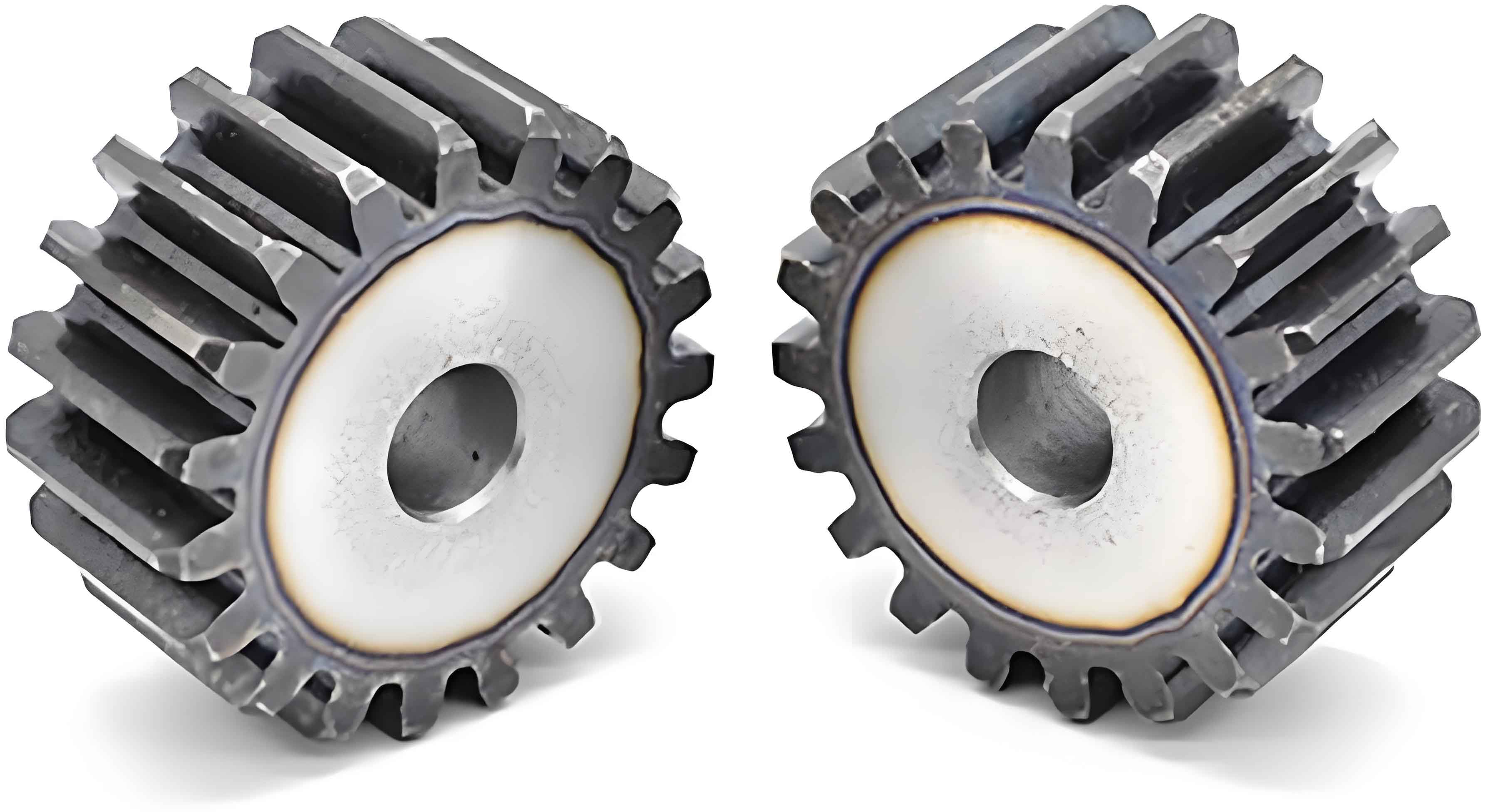
Cylindrical gear transmission has the advantages of high efficiency, smooth transmission, and strong bearing capacity, and is widely used in industries such as transportation, aviation, and shipbuilding. In order to meet the increasing transmission requirements and high-efficiency, cost-effective production processing needs, rapid and efficient chamfering has become a common process method for removing burrs after tooth profile processing. This article proposes a new chamfering method and conducts in-depth research.
Table 1. Comparison of Common Chamfering Methods
| Chamfering Method | Advantages | Disadvantages |
|---|---|---|
| Manual Chamfering | Flexibility | Low efficiency, difficult to control chamfering effect |
| Grinding Chamfering | High precision | Low efficiency, high cost |
| Extrusion Chamfering | High efficiency | May cause tooth surface swelling,不利于 subsequent finishing processes |
2. Mathematical Model of the Rotational Indexing Chamfering Swept Surface
Rotational indexing machining refers to a processing method where the workpiece rotates simultaneously with the tool, achieving cutting and indexing during the rotation.
Table 2. Coordinates and Parameters of the Gear Tooth Profile
| Parameter/Coordinate | Symbol | Description |
|---|---|---|
| Involute development angle | u | – |
| Base circle radius | rb | – |
| Left tooth profile coordinates | (xL, yL, zL) | – |
| Base circle tooth space half-angle | ηb | – |
| Gear modification coefficient | x | – |
| Number of teeth | z | – |
| Normal pressure angle | αn | – |
| Transverse pressure angle | αt | – |
3. Construction of the Tool’s Rake Face and Flank Face
The milling chamfering tool mainly consists of three parts: the cutting edge, the rake face, and the flank face. The intersection line of the rake face and the flank face is the cutting edge.
Table 3. Design Parameters of the Rake Face
| Parameter | Symbol | Description |
|---|---|---|
| Tool rake angle | γt | Affects the sharpness of the cutting edge and cutting force |
| Normal vector of the rake face plane | nE | Determines the orientation of the rake face |
Table 4. Design Parameters of the Flank Face
| Parameter | Symbol | Description |
|---|---|---|
| Tool relief angle | αd | Ensures no interference during cutting |
| Tool helix angle | βt | Avoids interference and ensures smooth cutting |
4. Chamfering Cutting Simulation Experiment
In order to verify the correctness of the mathematical model, a chamfering cutting simulation experiment was conducted on a multi-axis NC machining simulation platform.
Table 5. Workpiece Gear Parameters
| Parameter | Value |
|---|---|
| – (Example parameter, specific values depend on the experiment) | – |
Table 6. Tool Basic Parameters and Rotational Indexing Chamfering Installation Parameters
| Parameter | Value |
|---|---|
| Installation height H | 21 mm |
| Center distance P | 68.69 mm |
| Installation angle Σ | 6° |
| Chamfering depth | 0.5 mm |
Table 7. Measurement Results of Chamfering Depth
| Measurement Point Sequence | Chamfering Depth (mm) |
|---|---|
| 1 | 0.506 |
| 2 | 0.508 |
| 3 | 0.500 |
| 4 | 0.495 |
| 5 | 0.491 |
| 6 | 0.505 |
| 7 | 0.503 |
5. Conclusion
This article proposes a chamfering method based on rotational indexing for the efficient chamfering of cylindrical gear end faces. By analyzing the motion of rotational indexing chamfering, a mathematical model of the swept surface is established, providing a theoretical basis for rotational indexing chamfering. The construction process of the rake face and flank face of the rotational indexing chamfering tool is described, which can provide a reference for the design and optimization of the tool. Simulation experiments demonstrate that the method can achieve continuous indexing and efficient end face chamfering of gears, with good consistency in chamfering depth.
