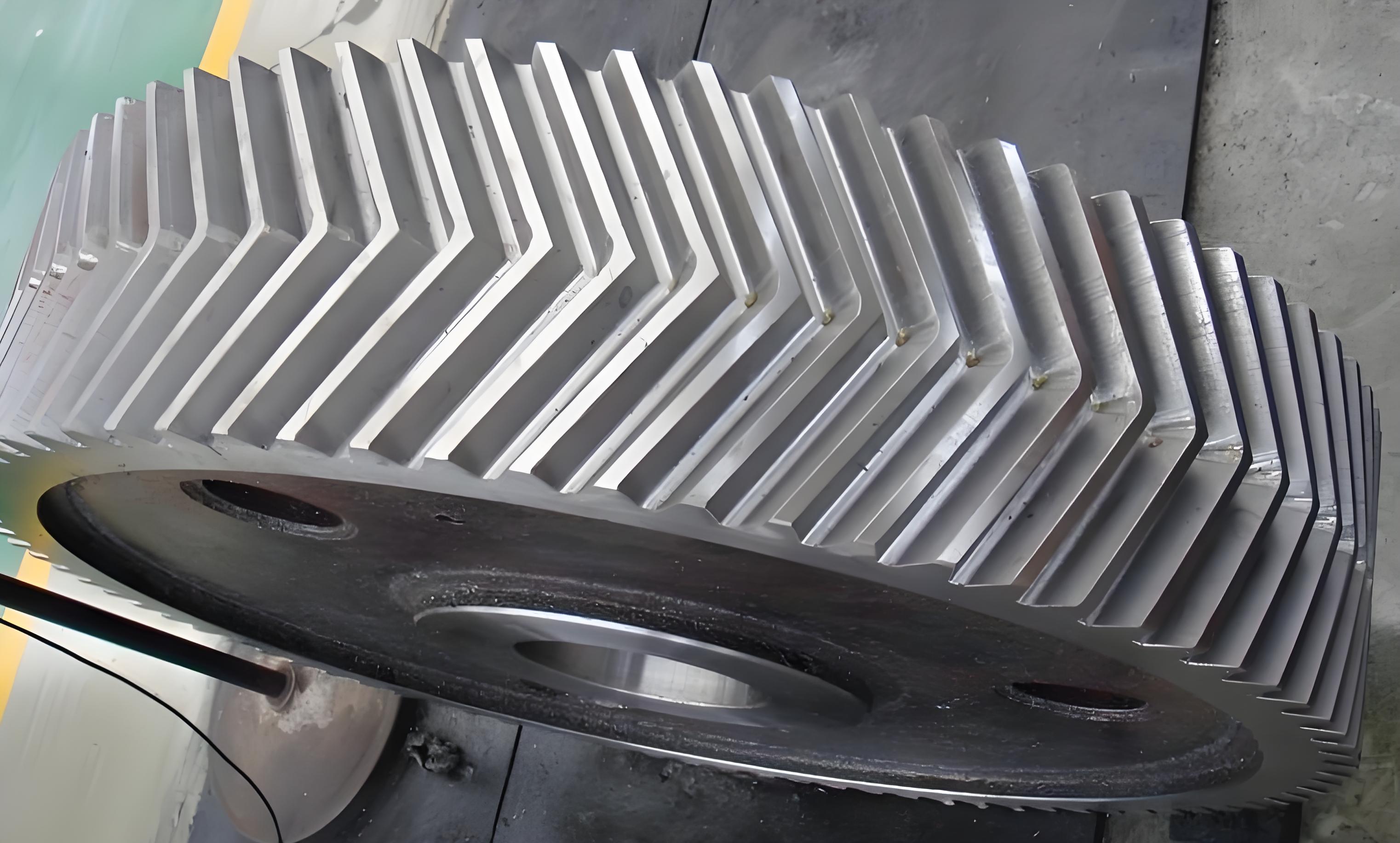
Herringbone gears combine the high load-bearing capacity of helical gears with the elimination of axial forces, making them critical components in high-speed, heavy-duty applications such as aerospace and marine systems. However, manufacturing-induced symmetry deviations lead to uneven load distribution, significantly impacting gear lifespan and operational efficiency. This study proposes a systematic methodology to characterize and measure symmetry deviations in herringbone gears, supported by experimental validation and finite element analysis.

1. Symmetry Deviation Characterization
Symmetry deviation in herringbone gears manifests as positional and angular mismatches between the left- and right-handed helical gear sections relative to the symmetry midplane. These deviations are decomposed into four components:
$$L_s = r_b \cdot \Delta\phi$$
$$L_R = R_1 – R_2$$
$$L_\alpha = \frac{\Delta Z}{\sin(\Delta\alpha)}$$
$$L_\beta = \max(r_{k1}, r_{k2}) \cdot (\theta_{k1} – \theta_{k2})$$
Where $L_s$ represents circumferential distance deviation, $L_R$ radial distance deviation, $L_\alpha$ helix angle deviation, and $L_\beta$ profile angle deviation. This decomposition enables precise quantification of asymmetry in herringbone gear pairs.
| Deviation Component | Calculation Formula |
|---|---|
| Circumferential Distance | $L_s = r_b \cdot \Delta\phi$ |
| Radial Distance | $L_R = R_1 – R_2$ |
| Helix Angle | $L_\alpha = \Delta Z / \sin(\Delta\alpha)$ |
| Profile Angle | $L_\beta = \max(r_{k1}, r_{k2}) \cdot \Delta\theta$ |
2. Measurement Methodology
A three-coordinate measuring machine (CMM) with specialized probe configurations was employed for feature line measurement. The process involves:
- Establishing coordinate system using gear end faces and bore axis
- Measuring spiral and profile lines on both gear sections
- Data processing through custom MATLAB algorithms
The measurement uncertainty analysis considers probe radius compensation and machine positioning errors:
$$x_0 = x_1 – R_c \cos(\alpha_a + \theta_a)$$
$$y_0 = y_1 + R_c \sin(\alpha_a + \theta_a)$$
| Error Source | Compensation Method | Improvement |
|---|---|---|
| Probe Radius | Geometric compensation | 0.89μm reduction |
| Positioning | Iterative alignment | 1.2-2.3μm accuracy |
3. Experimental Validation
Three aerospace herringbone gears were measured with the following parameters:
| Parameter | Value |
|---|---|
| Module | 3.8788 mm |
| Pressure Angle | 22.5° |
| Helix Angle | 30° |
| Face Width | 47 mm |
Measurement results demonstrate strong correlation with commercial gear analysis software (Quindos):
| Deviation Type | CMM Measurement | Quindos Result |
|---|---|---|
| Helix Total | 23.2μm | 20.1μm |
| Profile Total | 13.4μm | 11.8μm |
4. Impact on Meshing Characteristics
Finite element analysis reveals significant effects of symmetry deviations on load distribution:
$$F_{\text{max}} = F_0 \cdot \left(1 + k_1L_s + k_2L_R + k_3L_\alpha + k_4L_\beta\right)$$
Where $k_i$ represents sensitivity coefficients. The profile angle deviation $L_\beta$ shows the strongest impact with 24.5% stress increase at 12.6μm deviation.
| Deviation Component | Stress Increase |
|---|---|
| $L_s$ (26.7μm) | 3.99% |
| $L_R$ (17.6μm) | 8.12% |
| $L_\beta$ (12.6μm) | 24.5% |
5. Conclusion
This study establishes a comprehensive framework for symmetry deviation characterization in herringbone gears, combining theoretical modeling, precision measurement, and numerical simulation. The proposed four-component deviation model provides critical insights for manufacturing quality control and gear system optimization. Future work will focus on developing standardized evaluation protocols and real-time monitoring systems for industrial applications.
