
In this investigation, I examine how the material choice for the column of a CNC spiral bevel gear machining machine affects static stiffness, modal behavior, and harmonic response. The column is one of the most important structural loops in gear machining equipment because it connects the bed, the saddle, and the spindle-related assemblies while maintaining the geometric relationship required for accurate tooth flank generation. In gear machining, even small static deflections or lightly damped vibrations can be transferred to the cutting interface, where they alter contact patterns, tooth thickness, surface waviness, and transmission error. Therefore, I treat the column not merely as a supporting casting but as a dynamic component that directly participates in the accuracy chain of gear machining.
My work is motivated by a practical question: can a rock-based polymer composite replace conventional cast iron or natural granite in a CNC spiral bevel gear machining machine column without sacrificing static and dynamic performance? To answer this question, I use ANSYS Workbench to compare three material cases: a rock-based polymer composite, gray cast iron HT250, and natural granite. I evaluate the maximum static deformation, the maximum equivalent stress, the first six natural frequencies, the associated mode shapes, and the maximum harmonic response amplitudes in the X, Y, and Z directions. I also derive several comparative indices to quantify the benefits for gear machining accuracy, structural mass, and vibration suppression.
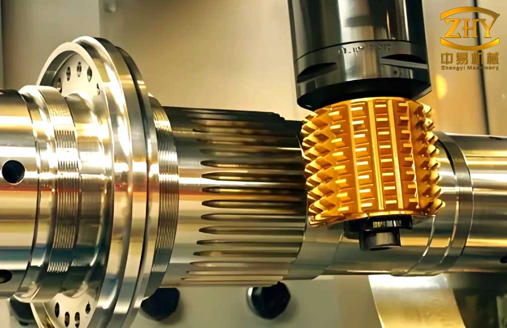
Material system and properties. The rock-based polymer composite I study is a composite material made from basalt particles as aggregate, epoxy resin and hardener as binder, and small amounts of reinforcement and accelerator. Its appeal for gear machining machine tools comes from a combination of high internal damping, good corrosion resistance, thermal stability, design flexibility, and the ability to retain dynamic accuracy over long periods. Unlike conventional metallic castings, the composite can be molded into complex ribbed and pocketed geometries, which helps me place stiffness where the gear machining load path requires it while reducing unnecessary mass. Table 1 summarizes the main technical parameters that I use in the finite element model.
| Technical parameter | Rock-based polymer composite | Cast iron HT250 | Natural granite |
|---|---|---|---|
| Density (g/cm³) | 2.5–2.9 | 6.6–7.4 | 3.0–4.5 |
| Compressive strength (N/mm²) | 180–420 | 300–900 | 200–300 |
| Bending strength (N/mm²) | 40–120 | 100–300 | 20–30 |
| Elastic modulus (N/mm²) | 55–135 | 80–120 | 50–100 |
| Thermal conductivity (W/(m·K)) | 1.6–2.0 | 40–50 | 2.5–3.5 |
| Poisson’s ratio | 0.25 | 0.2–0.3 | 0.2–0.3 |
| Damping coefficient | 0.30 | 0.001–0.002 | 0.002–0.003 |
The damping coefficient is especially important for gear machining. The rock-based polymer composite has a damping coefficient around 0.30, while HT250 and granite have damping coefficients in the range of 0.001–0.003. This difference of two orders of magnitude means that, even when the elastic modulus and density are not drastically different, the composite can dissipate vibration energy much more effectively. For gear machining, this damping behavior is valuable because the cutting process generates periodic excitation from tooth engagement, spindle rotation, and servo motion. If those excitations are not attenuated, they can appear as ripple on the gear tooth surface, variation in tooth contact, and increased transmission error.
I also use two simple material selection indices. The specific stiffness index is
$$
S = \frac{E}{\rho},
$$
where \(E\) is the elastic modulus and \(\rho\) is the density. The specific damping-stiffness index is
$$
\Lambda = \frac{\zeta E}{\rho},
$$
where \(\zeta\) is the damping coefficient. For gear machining columns, \(\Lambda\) is often more informative than \(S\) alone because it rewards both stiffness and damping. However, since the final deformation and frequency also depend on the geometry and boundary conditions, I do not rely on these indices alone; I use them only as a guide when interpreting the finite element results.
Finite element model of the column. I constructed a three-dimensional solid model of the column at a 1:1 scale and simplified small geometric details such as chamfers, fillets, and minor grooves. These details have a negligible influence on the global static and dynamic behavior of the column, but they can greatly increase the number of elements and the computation time. After simplification, I imported the model into ANSYS Workbench and assigned the material properties from Table 1. I used the same geometry, mesh, constraints, and loads for all three material cases so that the comparison isolates the effect of material choice. This is important for gear machining because it allows me to attribute differences in deformation, frequency, and amplitude to the material rather than to geometric changes.
The mesh was generated with an automatic method and a smart size of 20 mm. The final mesh contains 512,411 elements and 309,427 nodes. The average element quality is 0.74, and the average skewness is 0.35. These values indicate that the mesh is suitable for the intended static and dynamic analyses. Table 2 lists the mesh and model details.
| Item | Value |
|---|---|
| Model scale | 1:1 |
| Simplified features | Chamfers, fillets, small grooves |
| Mesh method | Automatic |
| Smart size | 20 mm |
| Number of elements | 512,411 |
| Number of nodes | 309,427 |
| Average element quality | 0.74 |
| Average skewness | 0.35 |
The column is connected to the bed by ten bolts. I represent this connection as a fully constrained interface because the contact deformation of the bolted joint is small compared with the global deformation of the column. I do not include damping and inertia effects in the static analysis, but I include structural damping in the harmonic response analysis. According to the actual working condition of the CNC spiral bevel gear machining machine, I apply a fixed support at the bolted interface, a horizontal uniform load on the guideway surfaces, and a torque on the B-axis mounting surface. Table 3 summarizes the boundary conditions and loads.
| Boundary condition or load | Description |
|---|---|
| Fixed support | Ten-bolt connection between column and bed |
| Guideway load | Horizontal uniform load on guideway surfaces |
| B-axis mounting surface | Applied torque |
| Coordinate system | X, Y, and Z axes aligned with machine axes |
| Static damping | Not considered |
| Harmonic damping | Structural damping included |
Static analysis formulation. The static equilibrium of the column is governed by
$$
[K]\{u\} = \{F\},
$$
where \([K]\) is the global stiffness matrix, \(\{u\}\) is the nodal displacement vector, and \(\{F\}\) is the applied load vector. The strain and stress fields are obtained from
$$
\{\varepsilon\} = [B]\{u\},
$$
$$
\{\sigma\} = [D]\{\varepsilon\},
$$
where \([B]\) is the strain-displacement matrix and \([D]\) is the elastic constitutive matrix. The maximum deformation is
$$
\delta_{\max} = \max_{\Omega} \|u(x,y,z)\|_2,
$$
and the maximum equivalent stress is
$$
\sigma_{\mathrm{vM,max}} = \max_{\Omega} \sigma_{\mathrm{vM}}(x,y,z).
$$
The structural mass is
$$
m = \int_{\Omega} \rho \, d\Omega.
$$
For comparison, I define the deformation reduction relative to a reference material as
$$
R_{\delta} = \frac{\delta_{\mathrm{ref}} – \delta}{\delta_{\mathrm{ref}}} \times 100\%,
$$
and the mass reduction as
$$
R_{m} = \frac{m_{\mathrm{ref}} – m}{m_{\mathrm{ref}}} \times 100\%.
$$
These quantities are useful for gear machining because lower deformation helps preserve the geometric relationship between the tool and the workpiece, while lower mass can improve the dynamic response of the machine axes and reduce the burden on the drive system.
Table 4 presents the static analysis results. The maximum deformation of the rock-based polymer composite column is 15.923 μm. The corresponding values for the HT250 column and the granite column are 17.941 μm and 28.732 μm, respectively. Therefore, the composite column reduces the maximum deformation by 11.25% compared with the HT250 column and by 44.58% compared with the granite column. This result is significant for gear machining because the column deformation participates directly in the machine tool loop. When the column deflects under cutting load, the relative position between the cutter and the gear blank changes, which can alter the tooth profile, lead, and contact pattern. A reduction of 11.25% relative to cast iron and 44.58% relative to granite is therefore not merely a structural number; it is a potential improvement in gear machining accuracy.
| Material | Maximum deformation (μm) | Maximum equivalent stress (MPa) |
|---|---|---|
| Rock-based polymer composite | 15.923 | 5.4 |
| Cast iron HT250 | 17.941 | 5.4 |
| Natural granite | 28.732 | 5.4 |
The maximum equivalent stress is 5.4 MPa for all three materials. This value is far below the allowable stress of each material, which indicates that the column design is not strength-limited under the applied static load. Instead, the design is governed by stiffness, mass, and dynamic behavior. This is a common situation in precision gear machining machine tools, where the allowable stress is rarely the limiting factor but the static and dynamic stiffness are critical for accuracy. The composite material therefore has a further advantage: it can provide adequate stiffness and strength while reducing mass and increasing damping.
Modal analysis formulation. The dynamic behavior of the column can be represented as a damped multi-degree-of-freedom system:
$$
[M]\ddot{X} + [C]\dot{X} + [K]X = F(t),
$$
where \([M]\) is the mass matrix, \([C]\) is the damping matrix, \([K]\) is the stiffness matrix, \(\ddot{X}\) is the acceleration vector, \(\dot{X}\) is the velocity vector, \(X\) is the displacement vector, and \(F(t)\) is the excitation vector. In the frequency domain, this equation becomes
$$
\left(K – \omega^2 M + j\omega C\right)X(\omega) = F(\omega).
$$
The response at any point \(l\) can be expressed as a linear combination of modal responses:
$$
X_l = \sum_{r=1}^{N} \phi_{lr} q_r(\omega),
$$
where \(\phi_{lr}\) is the mode shape coefficient of mode \(r\) at point \(l\), and \(q_r(\omega)\) is the modal coordinate. The modal vector is
$$
\phi_r = \{\phi_1, \phi_2, \ldots, \phi_N\}_r^T.
$$
After decoupling, the modal equation is
$$
\left(K_{\mathrm{dia}} – \omega^2 M_{\mathrm{dia}} + j\omega C_{\mathrm{dia}}\right)Q = F_{\phi},
$$
where \(K_{\mathrm{dia}}\), \(M_{\mathrm{dia}}\), and \(C_{\mathrm{dia}}\) are diagonal modal matrices, and \(F_{\phi} = \phi^T F(\omega)\). The damping matrix is often represented by Rayleigh damping:
$$
[C] = \alpha [M] + \beta [K],
$$
where \(\alpha\) and \(\beta\) are mass-proportional and stiffness-proportional damping coefficients. For the composite column, the high material damping means that the effective damping matrix has a much larger contribution than it does for cast iron or granite. This is one of the main reasons why the composite column performs better in harmonic response.
I analyze the first six modes because the lower modes dominate the global dynamic behavior of the column. The excitation frequency range is set to 0–300 Hz because the spindle speed of the machine tool is below 15,000 r/min. Table 5 lists the natural frequencies. The rock-based polymer composite column has natural frequencies of 391.78, 489.18, 569.77, 1007.00, 1063.10, and 1202.00 Hz. The HT250 column has frequencies of 228.40, 285.30, 332.33, 586.19, 619.47, and 700.38 Hz. The granite column has frequencies of 250.96, 313.40, 365.10, 644.40, 680.70, and 769.71 Hz. All first six natural frequencies of the composite column are above 300 Hz, while the first natural frequencies of the HT250 and granite columns are below 300 Hz.
| Mode | Rock-based polymer composite (Hz) | Cast iron HT250 (Hz) | Natural granite (Hz) | Mode shape description |
|---|---|---|---|---|
| 1 | 391.78 | 228.40 | 250.96 | Upper column torsion about Z axis |
| 2 | 489.18 | 285.30 | 313.40 | Upper column fore-aft sway along Y axis |
| 3 | 569.77 | 332.33 | 365.10 | Side of column lateral sway along X axis |
| 4 | 1007.00 | 586.19 | 644.40 | Left side of column torsion about Y axis |
| 5 | 1063.10 | 619.47 | 680.70 | Upper column torsion about X axis |
| 6 | 1202.00 | 700.38 | 769.71 | Upper column fore-aft sway along Z axis |
The frequency margin relative to the spindle excitation can be written as
$$
M_f = \frac{f_1 – f_{\mathrm{spindle}}}{f_{\mathrm{spindle}}} \times 100\%.
$$
If I take the upper spindle excitation frequency as 300 Hz, the first natural frequency of the composite column is 391.78 Hz, which gives a margin of
$$
M_f = \frac{391.78 – 300}{300} \times 100\% = 30.59\%.
$$
This is larger than the 15% minimum margin that I consider desirable for safe gear machining operation. By contrast, the first natural frequency of the HT250 column is 228.40 Hz, which is below 300 Hz, and the first natural frequency of the granite column is 250.96 Hz, which is also below 300 Hz. This means that both conventional material columns may enter resonance or near-resonance conditions within the operating speed range, while the composite column avoids the main excitation band. For gear machining, this is a decisive advantage because resonant vibration can produce severe tooth surface errors, chatter marks, and accelerated tool wear.
Table 6 shows the first-frequency margin for each material. The composite column not only avoids the 0–300 Hz excitation range but also provides a comfortable separation from the spindle frequency. This separation is important in gear machining because the cutting force contains multiple harmonics from tooth engagement. Even if the fundamental spindle frequency is below 300 Hz, higher harmonics can appear, and a column with a higher first natural frequency is less likely to be excited by those harmonics.
| Material | First natural frequency (Hz) | Spindle upper frequency (Hz) | Margin (%) |
|---|---|---|---|
| Rock-based polymer composite | 391.78 | 300 | 30.59 |
| Cast iron HT250 | 228.40 | 300 | -23.87 |
| Natural granite | 250.96 | 300 | -16.35 |
Harmonic response analysis. I use the modal superposition method in ANSYS Workbench to perform the harmonic response analysis. The frequency range is 0–300 Hz, and the step size is 30 Hz. I apply the same excitation amplitude as in the modal analysis and use the top surface of the column as the reference surface. The structural damping is included. The harmonic response can be written as
$$
X(\omega) = H(\omega) F(\omega),
$$
where the frequency response function is
$$
H(\omega) = \left(-\omega^2 M + j\omega C + K\right)^{-1}.
$$
The maximum amplitude in each direction is
$$
A_x = \max_{\omega} |X_x(\omega)|, \quad
A_y = \max_{\omega} |X_y(\omega)|, \quad
A_z = \max_{\omega} |X_z(\omega)|.
$$
I also define the amplitude reduction relative to a reference material as
$$
R_A = \frac{A_{\mathrm{ref}} – A}{A_{\mathrm{ref}}} \times 100\%.
$$
Table 7 lists the maximum response amplitudes in the X, Y, and Z directions for the three material cases. The composite column has the smallest amplitude in every direction. In the X direction, the maximum amplitude is 0.51 × 10⁻³ mm for the composite, 1.06 × 10⁻³ mm for HT250, and 1.73 × 10⁻³ mm for granite. In the Y direction, the values are 1.63 × 10⁻³ mm, 1.97 × 10⁻³ mm, and 3.14 × 10⁻³ mm. In the Z direction, the values are 2.75 × 10⁻³ mm, 3.33 × 10⁻³ mm, and 5.35 × 10⁻³ mm.
| Direction | Rock-based polymer composite (mm) | Cast iron HT250 (mm) | Natural granite (mm) |
|---|---|---|---|
| X | 0.51 × 10⁻³ | 1.06 × 10⁻³ | 1.73 × 10⁻³ |
| Y | 1.63 × 10⁻³ | 1.97 × 10⁻³ | 3.14 × 10⁻³ |
| Z | 2.75 × 10⁻³ | 3.33 × 10⁻³ | 5.35 × 10⁻³ |
Table 8 presents the percentage reductions. Compared with the HT250 column, the composite column reduces the maximum amplitude by 51.89% in X, 17.26% in Y, and 17.42% in Z. Compared with the granite column, the composite column reduces the maximum amplitude by 70.52% in X, 48.09% in Y, and 48.60% in Z. These reductions are substantial for gear machining. The X direction is often associated with the lateral error that affects tooth lead and contact pattern. The Y direction is associated with depth-of-cut variation, and the Z direction is associated with axial positioning error. Reducing all three simultaneously improves the volumetric accuracy of the gear machining process.
| Direction | Reduction vs. HT250 (%) | Reduction vs. granite (%) |
|---|---|---|
| X | 51.89 | 70.52 |
| Y | 17.26 | 48.09 |
| Z | 17.42 | 48.60 |
The harmonic response results show that the composite column not only has higher natural frequencies but also lower peak amplitudes. This combination is ideal for gear machining because it means that the column is less likely to be excited and, even when it is excited, it dissipates the vibration energy more effectively. The high damping coefficient of the composite is the main reason for the lower amplitudes. In a gear machining process, the cutting force is not a single-frequency sinusoid; it contains contributions from spindle rotation, cutter runout, tooth passage, and servo dynamics. A column with high damping can attenuate these multiple frequency components, which helps produce a smoother tooth surface and a more stable contact pattern.
Comparative assessment. To compare the three materials more systematically, I define a normalized performance score. For a benefit-type index, the normalized score is
$$
s_i = \frac{x_i – x_{\min}}{x_{\max} – x_{\min}},
$$
and for a cost-type index, it is
$$
s_i = \frac{x_{\max} – x_i}{x_{\max} – x_{\min}}.
$$
I use four indices: static deformation, structural mass, first natural frequency, and maximum Z-direction harmonic amplitude. Table 9 shows a qualitative summary. The composite column has the lowest deformation, the lowest mass, the highest first natural frequency, and the lowest harmonic amplitude. The HT250 column has moderate deformation and frequency, but its mass is high and its damping is low. The granite column has the highest deformation and amplitude, and although its mass is lower than HT250, it still has low damping and lower strength.
| Index | Rock-based polymer composite | Cast iron HT250 | Natural granite |
|---|---|---|---|
| Static deformation | Best | Moderate | Worst |
| Structural mass | Best | Worst | Moderate |
| First natural frequency | Best | Worst | Moderate |
| Harmonic amplitude | Best | Moderate | Worst |
| Damping | Best | Worst | Poor |
| Corrosion resistance | Good | Poor | Good |
| Design flexibility | Good | Moderate | Poor |
The composite material also offers a mass advantage. Because the density of the composite is around 2.5–2.9 g/cm³, while HT250 is around 6.6–7.4 g/cm³ and granite is around 3.0–4.5 g/cm³, the composite column can be significantly lighter than a cast iron column. This mass reduction is beneficial for gear machining because it reduces the moving mass that the feed drives must accelerate and decelerate. In high-speed gear machining, lower moving mass can improve the achievable axis bandwidth and reduce residual vibration after rapid moves. It also reduces the thermal inertia of the structure, which can help maintain geometric accuracy during long machining cycles.
I can express the lightweight benefit as
$$
L = \frac{m_{\mathrm{HT250}} – m_{\mathrm{comp}}}{m_{\mathrm{HT250}}} \times 100\%.
$$
Using the density ranges in Table 1 and assuming the same nominal volume, the composite is approximately 56–66% lighter than HT250 and approximately 10–36% lighter than granite, depending on the exact grades. This is a substantial reduction for a large column. In gear machining, the column is often one of the heaviest stationary components; reducing its mass while maintaining or improving stiffness can lower the cost of the bed and foundation and improve the overall dynamic response of the machine.
The composite column also has better thermal behavior for precision gear machining. Its thermal conductivity is 1.6–2.0 W/(m·K), which is much lower than that of HT250. A lower thermal conductivity means that the column is less sensitive to short-term ambient temperature fluctuations, and it can also reduce the formation of local thermal gradients. Although the low thermal conductivity can also mean that internal heat from drives or bearings is not dissipated as quickly, the composite’s high damping and design flexibility allow internal cooling channels or thermal symmetry to be designed into the structure. For gear machining, thermal stability is critical because thermal deformation can change the center distance and the relative angle between the cutter and the workpiece, which directly affects tooth thickness and contact pattern.
Design implications for gear machining. The results of this study suggest several design rules for CNC spiral bevel gear machining machine columns. First, the column should be designed to avoid the spindle excitation band. The composite column has a first natural frequency of 391.78 Hz, which is above the 300 Hz upper bound of the spindle excitation. This gives a comfortable margin for gear machining. Second, the column should use the high damping of the composite to suppress the harmonics that inevitably appear in gear machining. The harmonic response amplitudes are lower in all three directions, which means that the cutting interface receives less vibration. Third, the column should be lightweight but stiff. The composite column has lower mass and lower static deformation than the reference columns, which helps the feed axes and reduces the inertial loads during gear machining.
The mode shapes also provide useful guidance. The first mode is torsion about the Z axis, the second is fore-aft sway along the Y axis, and the third is lateral sway along the X axis. These modes correspond to the main compliance directions of the column. In gear machining, the cutting force has components in all three directions, so it is not enough to stiffen only one direction. I therefore recommend adding ribs or internal walls that increase torsional stiffness about Z and bending stiffness in X and Y without adding excessive mass. The composite material is well suited for this because it can be molded into complex rib patterns that would be difficult or expensive to produce in cast iron or granite.
I also examined the sensitivity of the first natural frequency to elastic modulus and density. For a simple structure, the natural frequency scales as
$$
f \propto \sqrt{\frac{E}{\rho}}.
$$
If the elastic modulus increases by 10% while density remains constant, the frequency increases by approximately
$$
\frac{\Delta f}{f} \approx \frac{1}{2} \frac{\Delta E}{E} = 5\%.
$$
If the density decreases by 10% while the elastic modulus remains constant, the frequency increases by approximately
$$
\frac{\Delta f}{f} \approx -\frac{1}{2} \frac{\Delta \rho}{\rho} = 5\%.
$$
Table 10 shows the sensitivity results for small changes in material parameters. This analysis confirms that both stiffness and mass are important. However, the composite material already has a favorable combination of low density and adequate modulus, and its high damping provides an additional benefit that is not captured by the simple scaling law.
| Parameter change | Effect on first natural frequency |
|---|---|
| Elastic modulus +10% | Approximately +5% |
| Elastic modulus -10% | Approximately -5% |
| Density +10% | Approximately -5% |
| Density -10% | Approximately +5% |
| Damping +100% | No large change in natural frequency, but large reduction in resonant amplitude |
For gear machining, the most important consequence of these results is that the column should be treated as part of the accuracy loop. The static deformation affects the quasi-static geometry of the cut, while the dynamic response affects the surface finish and contact pattern. A material that improves both static and dynamic behavior is therefore highly desirable. The rock-based polymer composite satisfies this requirement because it reduces static deformation, increases natural frequencies, and reduces harmonic amplitudes. In my analysis, the composite column performs better than both HT250 and granite in all three categories.
Another important point is that the maximum equivalent stress is the same for all three materials at 5.4 MPa. This means that the column is not limited by strength under the applied load. The design can therefore be optimized for stiffness, damping, and mass rather than for strength. This is a favorable situation for composite design because the composite can be tailored with ribs, cores, and local reinforcements to maximize stiffness and damping without the same manufacturing constraints as cast iron. For gear machining, this freedom can be used to place material exactly where the load path requires it, which can further improve the dynamic performance of the machine.
Limitations and future work. I simplified the bolted connection as a fixed support, and I did not include thermal loads, joint nonlinearities, or the full machine tool loop. These simplifications are reasonable for a comparative material study, but they should be revisited in future work. A more detailed model could include the bed, saddle, spindle, and workpiece, as well as the contact stiffness of the guideways and bearings. It could also include thermal boundary conditions from motors, bearings, and the environment. These factors can influence the absolute values of deformation and frequency, although the relative comparison between materials is likely to remain valid.
Future work should also include experimental validation. A physical column made from the rock-based polymer composite could be tested with modal hammer excitation and harmonic shaker tests. The measured frequency response functions could be compared with the finite element predictions. In addition, a gear machining test could be performed to measure tooth surface roughness, contact pattern, and transmission error. This would provide direct evidence of how the column material affects gear machining quality. I also plan to explore topology optimization and multi-material design, where the composite is used in the most damping-critical regions and a stiffer material is used in the most stiffness-critical regions. This could lead to further improvements in gear machining accuracy and productivity.
Conclusions. In this study, I analyzed the static and dynamic behavior of a CNC spiral bevel gear machining machine tool column made from three materials: a rock-based polymer composite, cast iron HT250, and natural granite. I used ANSYS Workbench to perform static analysis, modal analysis, and harmonic response analysis. The main conclusions are as follows.
First, under the same static load, the rock-based polymer composite column has the smallest maximum deformation. The maximum deformation is 15.923 μm, compared with 17.941 μm for HT250 and 28.732 μm for granite. This corresponds to a reduction of 11.25% relative to HT250 and 44.58% relative to granite. The maximum equivalent stress is 5.4 MPa for all three materials, which is far below the allowable stress. Therefore, the column design is stiffness-driven rather than strength-driven, and the composite material provides a favorable stiffness-to-mass ratio for gear machining.
Second, the composite column has the highest natural frequencies. All first six natural frequencies are above 300 Hz, while the first natural frequencies of HT250 and granite are below 300 Hz. The first natural frequency of the composite column is 391.78 Hz, which is 30.59% above the upper spindle excitation frequency of 300 Hz. This margin reduces the risk of resonance during gear machining. The mode shapes show that the main deformations are torsion about Z, sway along Y, and sway along X, which means that the column should be stiffened in multiple directions. The composite material is well suited for this because it can be molded into complex ribbed structures.
Third, the composite column has the lowest harmonic response amplitudes. Compared with HT250, the maximum response amplitude is reduced by 51.89% in X, 17.26% in Y, and 17.42% in Z. Compared with granite, the reductions are 70.52%, 48.09%, and 48.60%, respectively. These reductions are due to the high damping coefficient of the composite, which is about two orders of magnitude larger than that of HT250 or granite. For gear machining, this means less vibration at the cutting interface, which can improve tooth surface finish, contact pattern, and tool life.
Fourth, the composite column is significantly lighter than the HT250 column and generally lighter than the granite column. The lower mass reduces the inertial load on the feed drives and can improve the dynamic response of the machine axes. The composite also has good corrosion resistance and design flexibility, which are valuable for long-term accuracy and for integrating complex functional features such as cooling channels and sensor pockets.
Overall, I conclude that the rock-based polymer composite is a strong candidate for the column of a CNC spiral bevel gear machining machine. It provides better static stiffness, higher natural frequencies, lower harmonic amplitudes, and lower mass than the conventional cast iron and granite alternatives. These advantages can translate directly into improved gear machining accuracy, better surface quality, longer tool life, and higher productivity. The results support the use of rock-based polymer composites in lightweight and high-performance gear machining machine tool structures.
In future gear machining machine designs, I recommend that the column be evaluated as part of the complete machine tool loop rather than as an isolated component. The interaction between the column, bed, saddle, spindle, and workpiece can be included in a system-level model. The material and geometry can then be optimized together to maximize static stiffness, dynamic stiffness, damping, and thermal stability. With the continued development of composite manufacturing, I expect that rock-based polymer composite columns will become more common in precision gear machining equipment, especially where high accuracy, high damping, and lightweight design are required.